


VI
CTORY
II V
HS Models
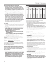
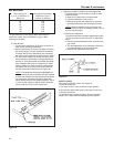
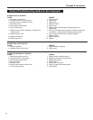
The gas metered in 3 minutes to obtain rated input for
e
ach boiler model, using 1000 Btu/cu. ft. gas, is tabu-
lated in gas rate table.
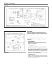
B. Main Burners
1. Fire the boiler continuously for at least 15 minutes, to
reach burner operating temperature.
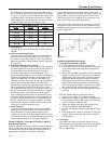
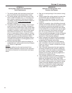
2. Observe the flames, all burners. The base of all flame
jets should be blue. The tips should be blue shading
to orange. NOTE: Dust, disturbed by any movement,
will cause bright orange flames. Wait for dust to settle.
3. For one burner, close the air shutter until some of its
flame jet tips turn yellow-white, indicating insufficient
primary air. Then open shutter until whitish tips disap-
pear completely. Set all burner shutters to the same
opening. Observe to make sure that no yellow-white
tips appear over any portion of the flame. Small yel-
low tips at the pilot are permitted (see Figure 18).
NOTE: This adjustment method gives MINIMUM pri-
mary air setting for safe combustion. DO NOT attempt
to make this adjustment unless burners are at operat-
ing temperature. Adjustment should be made with
burner access panel in final operating position. Use of
a mirror may be helpful to observe flames. Note that
burner ports are on top of main burner tube.
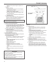
C. Main Burner Ignition Checkout and Pilot Adjustment
1. The pilot flame must not smother or snuff out when
t
ested as follows:
a. Main burner ignition from cold start-repeat.
b. Continued operation of main burner.
c
. Main burner ignition with appliance at maximum
operating temperature after prolonged operation.
N
O
T
E:
O
bserve operation of the pilot burner with
a
ppliance doors in the final operating position. Use of
a mirror may be helpful.
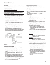
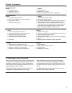
2. Pilot Burner Adjustment
T
he pilot flame should envelope approximately 3/8 to
1/2 inch of sensor tip (see Figure 19). To adjust pilot
flame:
a. Remove the pilot adjustment cover screw from the
gas control.
b. Turn pilot adjustment screw clockwise to decrease
or counterclockwise to increase pilot flame.
c. Replace pilot adjustment cover screw.
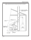
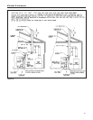
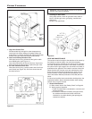
SAFETY CHECK
Removing Control Box (cover). See Figure 20.
To remove control box:
a. Turn black screw 1/4 turn clockwise to open position.
b. Remove two sheet metal screws in the top of control box.
c. Remove control box.
To replace the box, reverse procedure. Be sure that black
screw is in the lower bracket receptacle and lock position.
20
Boiler rated input in
cu. ft./hr. of 1000 Btu/cu. ft.
Natural Gas
30
60
90
120
150
1
80
Cubic Feet Gas Consumption
1
000 Btu/cu. ft. gas, in
3 minutes, at rated input
1.50
3
.00
4.50
6.00
7
.50
9.00
Figure 18.
Figure 19.
G
as Rate Table