


VI
CTORY
II V
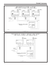
HS Models
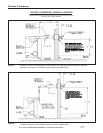
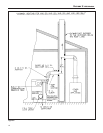
Figure 11a.
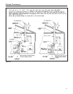
Figure 11b.
WATER PIPING
Always follow good piping practices. Observe minimum 1"
clearance to combustibles around all uninsulated hot water
pipes or when openings around pipes are not protected by
non-combustible materials.
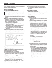
On a hot water boiler installed above radiation level, the boil-
er must be provided with a low water cutoff device at the time
of installation by the installer. (see Figure 15 for piping
arrangement)
1. Supply and Return
For tapping sizes see dimensions on page 2. Shut-off
valves are recommended.
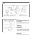
2. Circulating Systems
Victory II boilers are equipped with a water circulating
pump mounted to the return water connection on the
boiler. This pump location is appropriate for most installa-
tions. It may be desired and proper to locate this pump to
the alternate pump location shown in Figure 15, especially
when applied to larger systems using high-head pumps.
When the pump is removed there is a 11/2" FPT tapping
that the return pipe may be attached to.
3. Air Control System
Diaphragm type compression tank is used to control sys-
tem pressure. It must be installed at the boiler or between
boiler and supply main pump(s).
15