VI
CTORY
II V
HS MODELS
2
. Condensation drain trap inspection
C
heck condensation drain trap to be full of water. Check
for deterioration of the tubing. Check that trap is not
p
lugged. DO NOT operate the boiler without filling the
trap with water to prevent flue gas discharge into space.
The drain should extend to a floor drain or to a contain-
er which may require emptying periodically.
3. Piping inspection
Look at all water piping. There should be no leaks or
signs of leaks at any pipe joints or around the boiler.
4. System water pressure inspection
The temperature and pressure gauge indicates the
pressure in the boiler at each water temperature. For
most installations, it should indicate about 12 to 15 psi
pressure when temperature is about 70 to 100° F and
from 15 psi to 25 psi when temperature is up to 240° F.
FOR YOUR SYSTEM, there is one correct pressure for
each temperature. ASK YOUR INSTALLER OR SERVI-
CEPERSON TO EXPLAIN AND SHOW YOU.
Learn
what normal pressures to look for.
If pressure decreas-
es
from normal, your system is losing water. If pressure
rises from normal, the relief valve will open to relieve
the pressure. Call your service organization if pressures
are higher or lower than normal, and if the relief valve
spills water. Repair or adjustment is needed.
5. Unusual noise
Stand near the boiler and look and listen. As the burn-
ers start and shut off, there should be no unusual noise.
No fire should be visible coming out from the front of
the boiler when the burners start or run.
6. Boiler room air supply inspection
Ample air is required for your boiler to burn fuel cleanly
and safely. Check to make sure all air vents are open
and free of obstruction. Air needs are greatest in cold
weather.
WARNING: The flow of combustion and ventilating air
to the boiler should not be obstructed.
WARNING: If you find any problem during your
inspection, call for service immediately.
ANNUAL SERVICE TECHNICIAN INSPECTION
A trained and qualified service technician should per-
form these inspections before each heating season:
1. Safety check
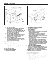
Removing Control Box (cover). See Figure 6. To
remove control box:
a. Turn back screw 1/4 turn clockwise to open
position .
b. Remove two sheet metal screws in the top of control
box.
c. Remove control box.
T
o replace the box, reverse procedure. Be sure that
black screw is in the lower bracket receptacle and
loc
k position .
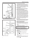
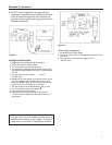
Figure 4. Vertical venting through chimney
Figure 5. Chimney venting
4


