


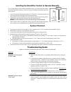

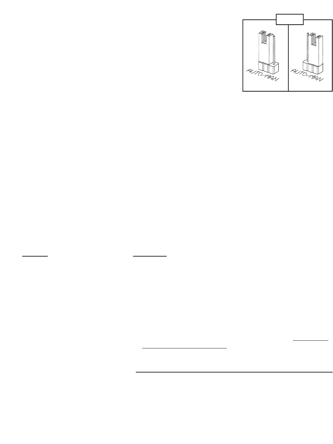
Installing the Humidifier Control to Operate Manually
If it is not possible to use the outdoor temperature sensor, or if the homeowner wants to
control the humidifier manually, Compustat can be reconfigured for manual operation.
(See Figure 9.)
1. Locate the three-pin arrangement marked “AUTO/MAN”, protruding from the con-
trol board (directly to the right of the wiring connections).
2. Pull upward to remove the black, two-pin connector from the auto position. Rein-
stall it in the manual position (on the center and right-hand pins).
NOTE: Do not attach sensor wire to the blue wiring connection block.
3. Follow Steps 8 and 9 to complete the wiring. Apply the manual-mode faceplate to
the Compustat cover. Reattach the cover to the base and reinstall the knob.
System Checkout
1. To conduct a system test, be sure that 24 VAC is applied to the 24 VAC terminals of the humidifier control.
2. Reattach the Compustat cover and knob to the base.
3. Activate the furnace blower and confirm that the thermostat is calling for heat.
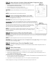
4. Rotate the knob on the humidifier control clockwise (
3) to the “Test” position.
• If everything is set up correctly, the humidifier should begin operating. In “Test” mode, Compustat will operate for
approximately one minute.
• If the humidifier does not activate properly in “Test” mode, refer to the Troubleshooting Guide, below.
5. Set the humidifier control.
• If the home is occupied, set the humidifier control knob to “5”. (For manual operation, set the knob to “35%”.)
• If the home is vacant, turn the humidifier control knob counterclockwise (
4) to “Off”.
6. Tell the homeowner to refer to the Compustat Operating Instructions for direction regarding initial adjustment.
Troubleshooting Guide
(applies to automatic and manual operation, unless otherwise indicated)
P
ROBLEM SOLUTION(S)
Humidifier does not operate
• Make sure the furnace blower is operating and the thermostat is calling for
in “Test” mode heat.
• Confirm that the outdoor temperature sensor is connected to the “Outdoor
Temperature Sensor” terminals on the humidifier control. (For manual op-
eration, make sure the jumper pins are positioned correctly.)
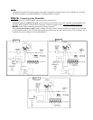
• Check the wiring diagrams (Figures 6-8) for correct installation.
• Check the voltage at the humidifier control “24 VAC” terminals. (Voltage
should be between 22 and 30 VAC.)
• Check the Model A50 relay (if used) for proper installation. (The relay is to
be wired to the “Out” circuit only!
)
• Make sure the control knob has not been left in the “Test” position. (In
“Test” mode, the humidifier will not continue to operate after approximately
one minute.)
Humidifier operates only in
• Check the resistance of the sensor by removing the leads from the humidifier
“Test” mode control terminals, and measuring the resistance across the wires with an
ohmmeter. Compare the reading to the temperature/resistance chart, which
follows.
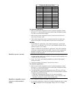
Temp. Resistance
Figure 9
Automatic Manual