


STEP 4: Select an Exterior Location to Mount the Outdoor Temperature Sensor
Placement of the outdoor temperature sensor must meet these requirements:
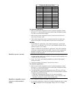
• It must be mounted on the North, Northeast or Northwest side of the house, where
direct sunlight will not influence the sensor.
• It must be placed at least 3 feet from all exhaust vents.
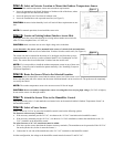
• It must be installed above the expected snow line (see Figure 3).
CAUTION: Incorrect indoor humidity levels will result if these requirements are not
met.
NOTE: For manual operation, do not install the sensor wire.
STEP 5: Locate an Existing Indoor/Outdoor Access Hole
If possible, insert the sensor cable through an existing indoor/outdoor access hole for
cable TV lines, telephone lines, A/C lines, etc.
CAUTION: Make sure there are no active high-voltage wires in the hole.
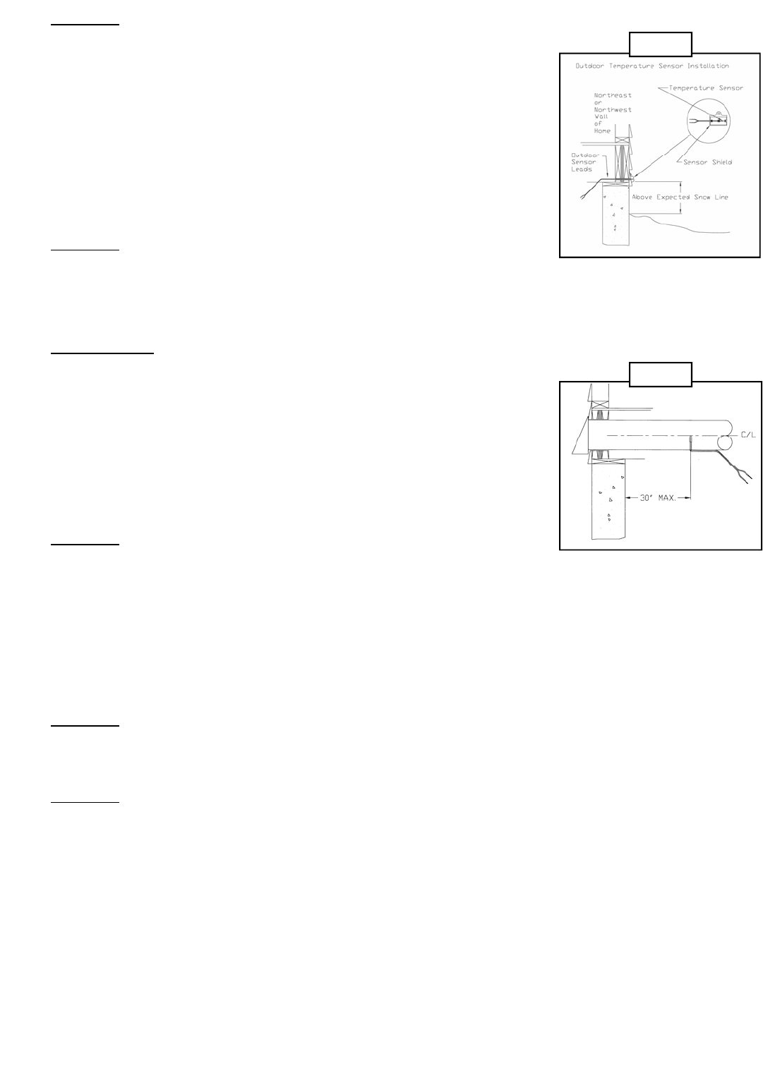
As an alternative
, the sensor can be mounted in the center of a 6-inch fresh air intake duct.
However, the sensor bulb must be no further than 30 inches from the outside wall. (See Figure 4.)
The sensor can also be mounted in the center of a 6 inch pipe used for make-up air or
combustion make-up air devices (such as a Skuttle Model 216 or Combustion Air Dif-
fuser). The sensor must be no further than 30 inches from the outside wall.
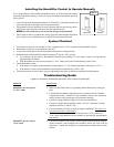
NOTE: If it is not possible to install the outdoor temperature sensor in any of these con-
figurations, Compustat can be installed to operate manually. (See “Installing Compustat
for Manual Operation”)
STEP 6: Route the Sensor Wire to the Selected Location
Run wire between the humidifier control and the outdoor sensor lead. If the sensor is out-
doors, snap the probe end of the sensor into the sensor shield and attach it to an exterior wall. The probe must be completely
covered by the shield.
NOTE: The outdoor temperature sensor wire must not exceed 30 feet in length.
CAUTION: Do not run outdoor temperature sensor wire alongside wires carrying high voltage (120 VAC or higher);
do not run the sensor wire through conduit.
STEP 7: Attach the Sensor Wire to the Humidifier Control
Strip the connecting wire 1/4" and attach the two internal wires to the terminals labeled “Outdoor Temperature Sensor” on
the humidifier control.
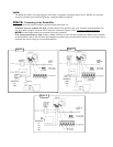
STEP 8: Select a Power Source
Select a source for 24 VAC to power the humidifier control, based on the following options:
For furnaces with accessory terminals…
• If the accessory terminals provide 24 VAC, wire them to the “24 VAC” terminals on the humidifier control.
• If the accessory terminals provide 120 VAC, wire them to a 24 VAC transformer; connect the transformer to the “24
VAC” terminals on the humidifier control.
For other furnaces, a 24 VAC transformer must be added.
• Wire into a power source other than the furnace accessory terminals. (The transformer can be powered off the 120 VAC
line at the junction box, before it enters the furnace.)
• Connect the 24-volt side of the transformer to the “24 VAC” terminals on the humidifier control.
In either configuration, the voltage to the humidifier control must be between 22 and 30 VAC.
Figure 3
Figure 4