


8
Attaching & Removing
the Turbo Vacuum Collector
WARNING
To operate without the collection system, the
blower assembly MUST be removed and the
deflector MUST be in the down position.
The deflector is spring loaded. when attaching or
removing the blower, hold the deflector up; then
allow the deflector to go down into the normal
operating position.
WARNING
The deflector is spring loaded. when attaching or
removing the blower, hold the deflector up; then
allow the deflector to go down into the normal
operating position.
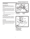
ATTACHING THE TURBO
1. Lift up the deflector.
2. Engage the stone guard hook at the bottom of the
turbo as shown in Figure 9.
3. Slide turbo assembly as far rearward as possible so
that the front turbo edge is tight against the front
mower deck edge. Secure the turbo with the hair pin
clip (B, Figure 8).
4. Move the idler release lever (C) to release belt ten-
sion.
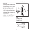
5. Route the belt as shown in Figure 11. Make sure it is
seated in all pulley grooves. The belt must be routed
to the inside of the 2-1/4" capscrew as shown in
Figure 11.
6. Close the belt cover (E. Figure 8) and tighten the
knob into the pal nut.
7. Make sure that deflector rests on upstop (D, Figure 8)
and does not contact the turbo housing. If deflector
contacts housing, use washer(s) as shims under the
upstop legs to increase clearance.
NOTE: After initial assembly, it is not necessary to
remove mower deck when removing or installing turbo
assembly.
REMOVING THE TURBO
NOTE: After initial assembly, it is not necessary to
remove mower deck when removing or installing turbo
assembly.
For operation without turbo, the deflector must be
properly installed in the down position and retained
by the spring latch.
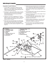
1. Disconnect the discharge tubes.
2. Unscrew the belt cover knob (C, Figure 10) and open
the cover.
3. Move the idler release lever (D, Figure 10) to release
tension on the drive belt and remove the belt from the
arbor pulley.
4. Remove the hairpin clip (B, Figure 10) and remove
the turbo assembly.
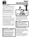
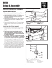
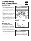
Figure 8. Mount Turbo
A. Mounting Plate D. Upstop
B. Hairpin Clip E. Belt Cover
C. Idler Release Lever
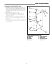
Figure 9. Engage Stone Guard Hook
D
C
B
A
E