


Electrical 7
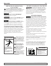
WIRING
Ground motor before connecting to electrical
power
supply. Failure to ground motor can cause severe or
fatal electrical shock hazard.
Do not ground to a gas supply line.
To avoid dangerous or fatal electrical shock, turn
OFF power to motor before working on electrical
connections.
Supply voltage must be within ±10% of nameplate
voltage. Incorrect voltage can cause fire or dam-
age motor and voids warranty. If in doubt consult a
licensed electrician.
Use wire size specified in Wiring Chart (Page 7). If
possible, connect pump to a separate branch cir-
cuit with no other appliances on it.
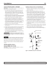
Wire motor according to diagram on motor name-
plate. If nameplate diagram differs from diagrams
above, follow nameplate diagram.
Step 1. Install, ground, wire and maintain this pump in
accordance with electrical code requirements.
Consult your local building inspector for informa-
tion about codes.
Step 2. Provide a correctly fused disconnect switch for pro-
tection while working on motor. Consult local or
national electrical codes for switch requirements.
Step 3. Disconnect power before servicing motor or
pump. If the disconnect switch is out of sight of
pump, lock it open and tag it to prevent unex-
pected power application.
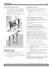
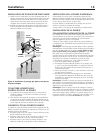
Step 4. Ground the pump permanently using a wire of
the same size as that specified in wiring chart,
below. Make ground connection to green ground-
ing terminal under motor canopy marked GRD.
or .
Step 5. Connect ground wire to a grounded lead in the
service panel or to a metal underground water
pipe or well casing at least 10 feet long. Do not
connect to plastic pipe or insulated fittings.
Step 6. Protect current carrying and grounding conduc-
tors from cuts, grease, heat, oil, and chemicals.
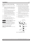
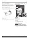
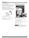
Step 7. Connect current carrying conductors to terminals
L1 and L2 under motor canopy. When replacing
motor, check wiring diagram on motor nameplate
against Figure 4. If the motor wiring diagram
does not match the diagram, follow the diagram
on the motor.
IMPORTANT: 115/230 Volt single phase models are
shipped from factory with motor wired for 230 volts. If
power supply is 115 volts, remove motor canopy and
change switch dial on motor as shown in Figure 4. Do
not try to run motor as received on 115 volt current.
Step 8. Motor has automatic internal thermal overload
protection. If motor has stopped for unknown
reasons, thermal overload may restart it unex-
pectedly, which could cause injury or property
damage. Disconnect power before servicing
motor.
Step 9. If this procedure or the wiring diagrams are con-
fusing, consult a licensed electrician.
For parts or assistance, call Simer Customer Service at 1-800-468-7867 / 1-800-546-7867
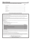
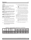
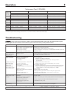
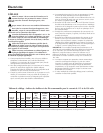
Wiring Chart – Recommended Wire and Fuse Sizes for 115 and 230 volts
Branch AWG
DISTANCE IN FEET(METERS) FROM MOTOR TO SUPPLY
Max. Fuse Min.
0 - 100 101 - 200 201 - 300 301 - 400 401 - 500
Pump Load Rating* Wire
(0 - 30) (31 - 61) (62 - 91) (92 - 122) (123 - 152)
Model HP Volts Amp Amp Size (mm
2
) AWG WIRE SIZE (mm
2
)
3410P 1 115/230 14.8/7.4 20/15 12/14 (3/2) 12/14 (3/2) 8/14 (8.4/2) 6/14 (14/2) 6/12 (14/3) 4/10 (21/5.5)
3415P 1-1/2 115/230 19.2/9.6 25/15 10/14 (5.5/2) 10/14 (5.5/2) 8/14 (8.4/2) 6/12 (14/3) 4/10 (21/5.5) 4/10 (21/5.5)
3420P 2 115/230 24/12 30/15 10/14 (5.5/2) 10/14 (5.5/2) 6/14 (14/2) 6/12 (14/3) 4/10 (21/5.5) 4/10 (21/5.5)
* Dual element or Fusetron time delay fuses recommended for all motor circuits.