


Installation 5
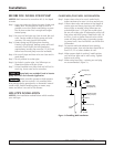
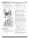
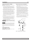
DRIVEN POINT INSTALLATION
Step 1. Connect suction pipe to drive point (Figure 2).
Keep horizontal pipe run as short as possible.
Use Teflon tape on male pipe threads. Multiple
well points may be necessary to provide suffi-
cient water to pump.
Step 2. Install check valve in horizontal pipe. Flow arrow
on check valve must point toward pump.
HORIZONTAL PIPING
FROM WELL TO PUMP
Step 1. Pump performance will be decreased if less that
1-1/2" pipe is used as suction pipe.
Step 2. To aid priming on well point installations, install
line check valve. Be sure check valve flow arrow
points toward pump.
DISCHARGE PIPE SIZES
Discharge pipe size should be increased to reduce pres-
sure losses caused by friction on long pipe runs.
• Up to 100' (30.5 m) run: Same size as pump dis-
charge port.
• 100' - 300' (30.5 - 91.4 m) run: Increase one pipe
size.
• 300' - 600' (91.4 - 182.9 m) run: Increase two pipe
sizes.
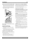
LAWN SPRINKLING APPLICATION
This pump is designed for lawn sprinkling. Delivers plen-
ty of water at full sprinkler pressure. Pumps from pond,
cistern or well points.
Pump discharge can be divided to supply 4 or more
sprinkler systems.
Do not use in booster pump applications.
PUMP/PIPING INSTALLATION
If turning pump on and off by pressure, a pressure switch
and tank are required. For proper installation and opera-
tion instructions call Customer Service.
Use rigid pipe. Do not use hose or plastic tubing. See
“Well Pipe Installation” for more information.
NOTICE: Use only Teflon tape or Teflon based joint com-
pounds for making all threaded connections to the pump
itself. Do not use pipe joint compounds on plastic
pumps: they can react with the plastic in pump compo-
nents. Make sure that all pipe joints in the suction pipe
are air tight as well as water tight.
If the suction pipe can
suck air, the pump will not be able to pull water from the
well.
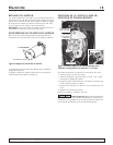
Step 1. Bolt pump to solid, level foundation.
Step 2. Support all piping connected to pump.
Step 3. Wrap 1-1/2 to 2 layers of Teflon tape clockwise
(as you face end of pipe) on all male threads
being attached to pump.
Step 4. Tighten joints hand tight plus 1-1/2 turns. Do not
overtighten.
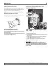
Step 5. Replace prime plug with pressure gauge. This
will aid in sizing zones, troubleshooting, and fol-
lowing pump performance chart.
NOTICE: Install pump as close to well head as possible.
Long piping runs and many fittings create friction and
reduce flow.
NOTICE: For long horizontal pipe runs, install a priming
tee between check valve and well head (Fig. 1). For dri-
ven point installations, install check valve. Be sure that
check valve flow arrow points toward pump.
For parts or assistance, call Simer Customer Service at 1-800-468-7867 / 1-800-546-7867
To sprinkler
heads
To sprinkler
heads
Gate
valve
Discharge
Pipe
Multiple well
points
Check
valve
Suction
Pipe
Figure 2: Driven Point Installation, Multiple Well Points