


New Deep Well Installation 7
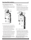
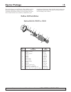
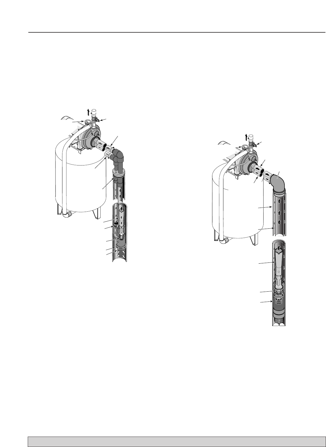
4" OR LARGER WELL (Figure 10)
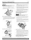
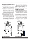
1. Install the control valve and pressure gauge in the
pump body. See Figure 7.
2. Assemble ejector kit FP4800 or 29660 (sold separate-
ly). See Figure 10. Follow the instructions included
with the kit in order to match the nozzle and venturi
to your well conditions.
3. Mount the pump as close to the well as possible.
4. Connect two pipes (1" drive, 1-1/4" suction) to the ejec-
tor and lower the ejector into the well until it is five feet
from the bottom. It should also be at least 10 feet
below the well’s water level while the pump is running
in order to prevent the pump from sucking air.
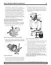
5. Install a sanitary well seal and connect the ejector
piping to the pump. Use steel nipples through the
well seal with flexible poly pipe to avoid crushing
the plastic pipe when tightening the seal.
6. Support the pipe so that there are no dips or sags in the
pipe, so it doesn’t strain the pump body, and so that it
slopes slightly upward from the well to the pump (high
spots can cause air pockets which can air lock the
pump). Seal the suction pipe joints with teflon tape or a
teflon based pipe joint compound. Joints must be air-
and water-tight. If the suction pipe can suck air, the
pump cannot pull water from the well.
You have just completed the plumbing for your new
double pipe deep well jet pump. Please go to Page 8 for
discharge pipe and tank connections.
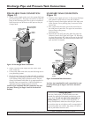
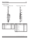
2" WELL (Figure 11)
1. Install the control valve and pressure gauge in the
pump body. See Figure 7.
2. Mount the pump as close to the well as possible.
3. Assemble ejector kit FP4840 or 29670 (sold separate-
ly), well piping, and well head adapter according to
the instructions provided with the ejector package.
See Figure 11. Use galvanized drop pipe with turned
couplings to allow proper flow. Follow the instruc-
tions included with the kit in order to match the noz-
zle and venturi to your well conditions.
4. Run two pipes (one smaller drive pipe, one larger
suction pipe) from the well to the pump. Support the
pipe so that there are no dips or sags in the pipe, so
it doesn’t strain the pump body, and so that it slopes
slightly upward from the well to the pump (high spots
can cause air pockets which can air lock the pump).
Seal the suction pipe joints with teflon tape or a
teflon based pipe joint compound. Joints must be air-
and water-tight. If the suction pipe can suck air, the
pump cannot pull water from the well.
You have just completed the plumbing for your new
single pipe deep well jet pump. Please go to Page 8 for
discharge pipe and tank connections.
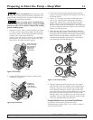
P
Suction (Larger)
Pipe from Well
To Household
Water System
Pressure
Gauge and
Priming
Plug
Well
Head
Drive (Smaller)
Line to Well
Venturi
Nozzle
Ejector
Not
to
Scale
Foot Valve
Strainer
266 0395
Relief Valve
For parts or assistance, call Simer Customer Service at 1-800-468-7867 / 1-800-546-7867
Figure 10: 4” and Larger Deep Well
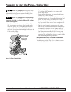
Figure 11: 2” (Single Pipe) Deep Well
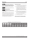
41
JET NO.
J32P-
24
P
Suction (Larger)
Pipe
from
Well
To Household
Water System
Pressure Gauge
and Priming
Plug
Well
Head
Drive (Smaller)
Pipe
to
Well
Well Casing
serves as
Drive Pipe
Suction Pipe
Venturi
Nozzle
Ejector
Not
to
Scale
267 0295
Relief Valve