


New Shallow Well Installation 5
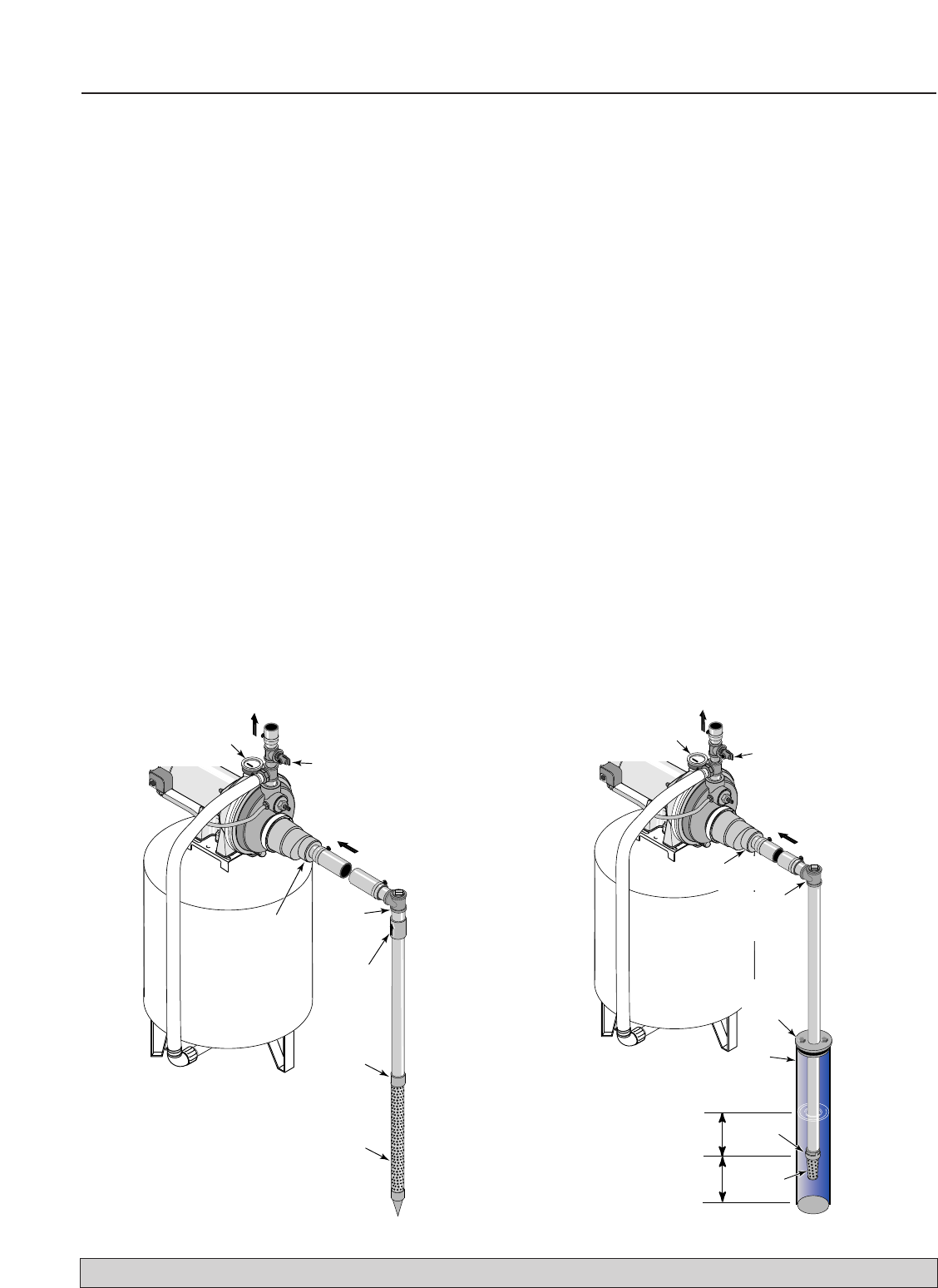
WELL POINT INSTALLATION (Figure 5)
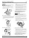
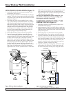
1. Install the control valve and pressure gauge in the
pump body (see Figure 1).
2. Install ejector kit FP4875 or 29650 (kits are sold sep-
arately). Follow the instructions provided with the kit.
Align the venturi with the top hole on the front of the
pump (see Figure 4).
3. Drive the well, using “drive couplings” and a “drive
cap”. “Drive fittings” are threaded all the way through
and allow the pipe ends to butt against each other so
that the driving force of the maul is carried by the pipe
and not by the threads. The ordinary fittings found in
hardware stores are not threaded all the way through
the fitting and can collapse under impact. “Drive fit-
tings” are also smoother than standard plumbing fit-
tings, making ground penetration easier.
4. Mount the pump as close to the well as possible.
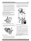
5. Use the fewest possible fittings (especially elbows)
when connecting the pipe from the well point to the
pump suction port. The suction pipe should be at least
as large as the suction port on the pump (include a
check valve – see Figure 5). Support the pipe so that
there are no dips or sags in the pipe, so it doesn’t strain
the pump body, and so that it slopes slightly upward
from the well to the pump (high spots can cause air
pockets which can air lock the pump). Seal the suction
pipe joints with teflon tape or pipe joint compound
approved for use on PVC. Joints must be air- and water-
tight. If the suction pipe can suck air, the pump cannot
pull water from the well. If one well point does not
supply enough water, consider connecting two or three
well points to one suction pipe.
You have just completed the suction piping for your
new shallow well jet pump. Please go to Page 8 for
discharge pipe and tank connections
CASED WELL INSTALLATION, 2" OR
LARGER CASING (Figure 6)
1. Install the control valve and pressure gauge in the
pump body (see Figure 1).
2. Install ejector kit FP4875 or 29650 (kits are sold sep-
arately). Follow the instructions provided with the kit.
Align the venturi with the top hole on the front of the
pump (see Figure 4).
3. Mount the pump as close to the well as possible.
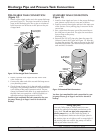
4. Assemble the foot valve, strainer, and well pipe (see
Figure 6). Make sure that the foot valve works freely.
5. Lower the pipe into the well until the strainer is five
feet above the bottom of the well. It should also be at
least 10 feet below the well’s water level while the
pump is running in order to prevent the pump from
sucking air. Install a sanitary well seal.
6. Install a priming tee, priming plug, and suction pipe
to the pump (see Figure 6). Connect the pipe from
the well to the pump suction port, using the fewest
P
222 0395
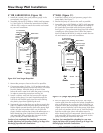
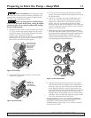
To Household
Water System
Suction Pipe
From Well
Priming
Tee and
Plug
Pressure Gauge
and Priming Port
Drive
Coupling
Drive
Point
Check
Valve
Built-in
Check
Valve
Not
to
Scale
Relief Valve
For parts or assistance, call Simer Customer Service at 1-800-468-7867 / 1-800-546-7867
Figure 5: Driven Point Installation
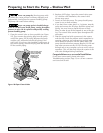
Figure 6: Cased Well Installation
P
256 0395
To Household
Water System
Suction Pipe
From Well
Pressure Gauge
and Priming Port
Priming
Tee and
Plug
Built-in
Check Valve
Not
to
Scale
Well
Casing
Foot
Valve
Sanitary
Well Seal
Strainer
5-10'
At least
10'
Relief Valve