


N
L
ON
OFF
CONTACTOR
12
HEATER
Red
Black
OUTLET
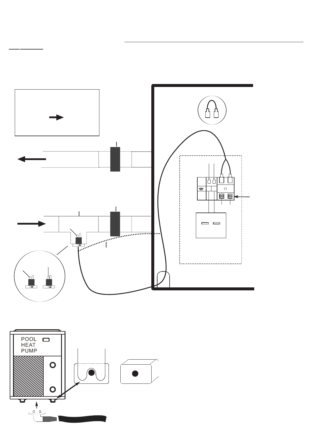
FLOW SWITCH
OPERATION
WATER FLOW
FROM PUMP
SOCKET
UNION
TEE
INLET
OFF
ON
Alternative wiring route
SOCKET
UNION
RETURN WATER
FLOW TO POOL
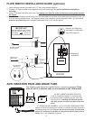
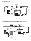
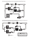
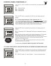
1. Insert reducing bushes (provided) into 1.5” Tee using suitable adhesive.
2. Connect 1.5” Tee to socket union adjacent to Inlet on heat pump. Tee can be installed horizontally or
vertically!
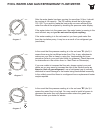
3. Using PTFE tape insert flow switch into Tee making sure that the arrow on the flow switch point
s towards
the heater.
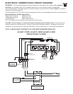
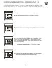
4. Turn off electrical supply to heat pump. Run the wire lead from the flow switch and make connection to No. 1 &
2 on the electric terminal block - see diagram below (wire extension may be required). Note:- you will have to
remove a pre-fitted loop that is already connected to No.1 & 2 see dia. below.
FLOW SWITCH INSTALLATION GUIDE (optional)
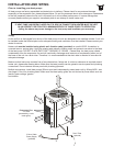
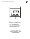
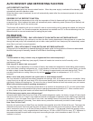
ANTI VIBRATION PADS AND DRAIN TUBE
X 4 ANTI VIBRATION PADS (PLASTIC)
Install on underside of heater. It is recommended
that Stainless Steel screws & plugs are used when
securing to floor. Installing anti vibration feet will
also help prevent corrsion to the base of the heat
pump.
1 X DRAIN VALVE (RUBBER) 1 X 2m FLEXIBLE DRAINAGE TUBE
Insert drain valve into drainage hole located on underside of heater and push fit
the drainage tube onto valve (Tip-you will find it much easier to insert drain
valve if it is immersed in hot water or sprayed with silicone spray prior to
fitting). Drain valve installation is optional.
The following parts should be installed prior to connecting pipework. Drain
tube will not fit if vibration pads are not installed on the 12kW model!
IMPORTANT
WHEN INSTALLING FLOW
SWITCH MAKE SURE THAT
ARROW POINTS
TOWARDS THE HEATER
6
Remove ‘pre-fitted loop’
and keep in a safe place
(See FAQ page 15).
Alternative
connection