


9
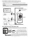
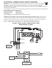
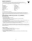
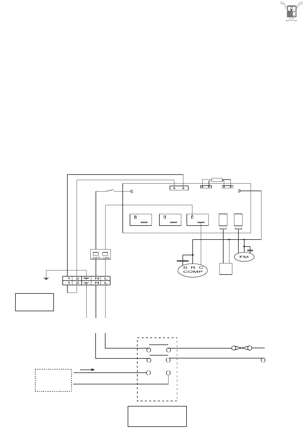
ELECTRICAL CONNECTION & CIRCUIT DIAGRAM
IMPORTANT. It is recommended that all electrical supplies and connections are carried out by a qualified
electrician, in accordance with I.E.E. standards, latest issue, or local codes of practice as applicable.
Also recommended is a protected supply to incorporate fuses or motor type circuit breaker (Type C) to specified
rating (see Data Sheet page 19).
An earth leakage trip (R.C.D) of the current operating type (30mA) is recommended to be fitted to all pool electric's.
Minimum/Maximum Voltage requirements.:
Single phase machines 50Hz 207v 253v
Three phase machines 50Hz 360v 440v
Cycle Frequency 50Hz 47.5Hz 52.5Hz
N.B. This voltage must be available at the heat pump whilst running.
A 40 AMP / 2 Pole Contactor is required to interlock heat pump and circulation pump i.e. heat pump only
functions when pool circulation pump is running. A flow switch (provided & optional - see page 5) can also be
installed as an extra precaution in the event that there is a loss of water flow (i.e. circulation pump deprimes).
NOTE - PLEASE CHECK CONTINUITY OF FLOW SWITCH BEFORE INSTALLING.
High Pressure
Protection
Flow Switch
Transformer
4-Way Valve
Compressor
Relay
Protective
Circuit Breaker
POWER SUPPLY
230V/50HZ
Link
or
Flow Switch
Heat Pump
Main Terminals
Remove Link to
wire flow switch
(see page 6)
L
N
A1
A2
CONTACTOR
40AMP 2 POLE
Contactor required to
interlock heat pump with
circulation pump
L
N
N
L
Control wires
from circulation
pump starter
AS-H40Y (12KW) AS-H50Y (15KW) AS-H60Y (18KW)
SINGLE PHASE (1-N 50HZ)