


5061 Brooks St. Montclair, CA 91763
909-399-3355 Fax 1-909-399-3357
www.sierraproductsinc.com
2 8
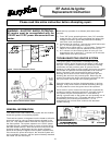
REMOVAL AND REPLACEMENT OF COMPONENTS
WARNING: RISK OF ELECTRIC SHOCK! REMOVE ALL POWER CORDS FROM UNIT BEFORE ATTEMPTING ANY
SERVICE.
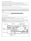
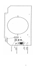
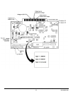
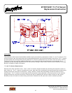
1. Circuit Board: The circuit board is located on the lower right hand side of the heater or insert (facing
from the front fig.1 - pg. 21).
Removal from Heater: Remove the two #8 phillips screws securing the panel to the pedestal side. Open the panel
by lifting up and out. Lay panel flat and remove two #8 phillips screws securing the control board stand-offs to the panel.
Gently remove board from 44 pin connector by firmly holding panel and pulling board toward you. Remove #8 nuts
attaching stands to the board and remove stands (these nuts are located on the lower right and left corners of the board).
Reverse the process to install new control board.
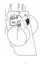
Removal from Insert: Remove the two #8 phillips screws securing the control cover from the hopper side.
Remove the two #8 phillips screws attaching the control board the stand-offs (these screws are located at the lower right
and left corners of the board). Gently remove board from 44 pin connector by pulling down on the board. Reverse the
process to install a new control board.
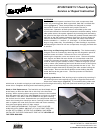
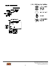
2. Fan Motor: The fan motor is located directly under the combustion fan housing. Access is provided through
the rear inspection covers on both the heater and insert. Remove the #8 screws attaching the covers. Remove the wire
harness leads to the motor noting there position both red and black. Next remove the plastic convection fan blade by
carefully pushing against the fan hub. Remove the four #10 nuts holding the fan motor base plate to the housing. Carefully
pry the base plate breaking the factory silicon seal. Remove motor from unit. Using a long allen wrench loosen the allen
set screws holding the combustion fan blades on the motor shaft. Remove the two #10 nuts holding the motor mount tho
the fan plate. Remove the two #8 phillips screws holding the motor mount to the motor. Reverse the process to replace fan
motor assembly.
NOTE: WHEN INSTALLING THE COMBUSTION FAN BLADES ON THE MOTOR SHAFT, USE LOCK TIGHT (RED)
ON THE ALLEN SET SCREWS. THE PROPER POSITION OF THE BLADES IS THE OUTER BLADE POSITIONED AT
THE END OF THE SHAFT AND THE SECOND BLADE TIGHT TO THE BACK OF THE FIRST. WHEN ASSEMBLING
THE FAN MOTOR PLATE BACK INTO THE UNIT, USE HIGH TEMPERATURE SILICONE SEAL ON CLEANED
MATING SURFACES.
Fan motor brushes maybe replaced by carefully removing the plastic screw caps on each side of the motor and replacing
with factory replacements.
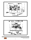
3. Control Switch: The control switch is located on the right side of both the heater and insert. In both units
remove the two #8 phillips screws holding the cover. Using a small blade standard screw driver carefully loosen the set
screw on the control knob. Next remove the 9/16 nut attached to the switch shaft. Remove the switch and unplug the
harness connector. Reverse procedure to install new
switch.
4. Transformer and Rectifier: The transformer and rectifier are located inside the cabinet on both the heater and
insert. Remove the inspection cover on the rear and locate the transformer. Remove the two #6 phillips screws and nuts.
Remove the wires noting the positions. Remove the transformer. The rectifier maybe removed by unplugging the wires
from the harness and transformer (note the position of the red and black harness wires). Remove the #6 phillips screw
and nut. Remove the rectifier. Reverse the procedure to install new parts.