


1 8
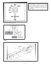
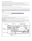
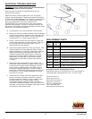
Component Adjustments and Replacement:
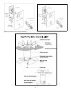
Main Control Board - Main control board is located in the lower right pedestal (3801/5001) or lower right rear - 4001 insert
and right switch plate for the 5001U. The control board is held in place with several phillips screws.
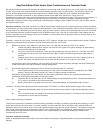
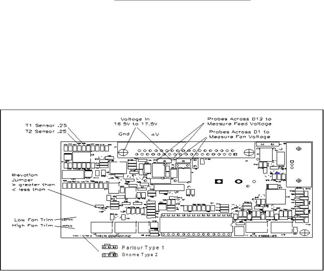
Fan speed adjustments are accomplished by turning the LOW and HIGH fan pots on the lower right corner. These
adjustments are made in the corresponding run mode. Factory settings are based on fan voltage as read across the motor
terminals 6.8VDC LOW, and 9.0VDC HIGH.
A GREEN LED light flashes on the control board to confirm AC or DC power is present.
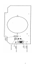
Switch Board - Switch board is attached to access panel with several phillips screws. Harness plugs into bottom of switch.
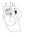
Sensors - Access for sensors is through the rear panels. Both the T-1 and T-2 sensors are the same sensor type mounted
differently. T-1 is mounted on the exhaust side of the combustion fan housing. It is held in place with a tie wrap. T-1 sensor
allows for cabinet air to drawn through the high temp plastic holder. When door is open or flue blocks the flow reverses. T-
2 sensor is attach to a aluminum block and attached to the manifold. Wire harness connections should be secure and not
pulled tight.
Additional information is available on line@ www.sierraproductsinc.net/pages/customer_service
Technical Customer Service - 909-399-3355x29
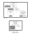
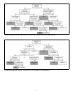
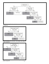
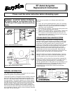
Red Light Fault Indications:
W hen the Hi-Temp/Flue indicator light comes on (red lite beneath control knob) it means a fault has been detected in
either the flue system, over temperature, or fan/feed motor.
Slow Flash Red Light - Indicates a blocked flue. Check flue and clean out for built up ash deposits.
Solid Red Light - Indicates an over temperature. Check the air intake at rear of unit. Turn the feed trim down 25% to
reduce fuel rate.
Fast Flash Red Light - Requires unit to be unplugged to reset. Indicates a feed motor jam or fan motor fault. Fan motor
test would require running unit on “fan and clean” only to determine if red light indication is repeated. If not, feed system is
jammed and requires the hopper access cover to be removed and jammed material to be removed