


4
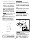
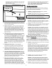
Figure 7 Rear Connection Panel
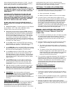
Figure 8 Stove Connection Panel
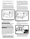
Autolite Wiring Diagram
UNIT INSTALLATION
Route the power supply cord so that it does not touch
any of the exterior components of the heater.
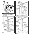
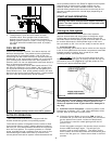
1. When exiting through the wall with your type L Pellet
vent pipe, you may go straight out through a wall
thimble. You must connect a pellet vent tee at this
point and extend the vent pipe at least 3' (three feet)
vertically outside to provide good draft and allow the
gases to exit. The tee must have a clean out cap for
inspection and regular cleaning (Figure 4). Horizontal
runs must be limited to 2' (two feet). A wall band is
required for every 4' (four feet) minimum on a vertical
run at an exterior wall.
2. All pellet vent pipe connections including exit at the
rear of the heater should be sealed with high
temperature silicone (450E) or metallic duct tape. This
prevents smoke and soot leakage into the living area.
If this is not done, there is a possibility that the room
fan will pick up any leakage and blow it into the room.
AUTOLITE INSTALLATION INSTRUCTIONS
The AutoLite System is factory installed with the only
installation requirements being the optional thermostat.
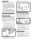
Wall Thermostat Installation:
The wall thermostat is designed to automatically regulate
the room temperature from the control panel heat setting
to the “Off” setting based upon room temperature.
Remember to leave the control panel on the "Medium or
High" position when utilizing the wall thermostat feature.
The following is a step by step procedure for installing the
optional wall thermostat. Note connection terminals on left
side of unit at rear (Figure 7,8). Use 18/2 thermostat wire
for the installation.
a. Unplug heater from wall outlet and 12VDC power!
b. Remove factory jump wire and hook up thermostat
wires to terminals (Figure 7,8).
c. Locate thermostat approximately 10 to 12 feet from
heater or in area that requires steady temperature.
d. Run thermostat wires from heater to thermostat
along wall or under carpet etc. and hook wires to
thermostat terminals. On new construction you
can, of course, run wire in the walls before sheet
rock or paneling is done.
e. Reconnect AC power.
f. Make sure all wiring is completed before plugging
the EASYFIRE Heater back into the wall outlet.
IMPORTANT - Any electrical work performed on the
EASYFIRE Heater should be done by qualified personnel.
Remote Control Thermostat Installation:
The remote thermostat is designed to automatically
regulate the room temperature from the control panel heat
setting to the “Off” setting based upon room temperature
and placement of the remote thermostat. Remember to
leave the control panel on the "Medium or High" position
when utilizing the wall thermostat feature.
The following is a step by step procedure for installing the
optional remote thermostat. Note connection terminals on
rear of unit (Figure 1,2).
a. Unplug heater from wall outlet and 12VDC power!
b. Mount millivolt style remote receiver box to rear of
stove using double-sided tape.
b . Remove factory jump wire and hook up thermostat
wires to terminals (Figure 7,8).
d. Reconnect AC power and follow instructions with
remote thermostat regarding set up.
IMPORTANT - Any electrical work performed on the
EASYFIRE Heater should be done by qualified personnel.
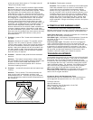
DOOR HANDLE ASSEMBLY
The door handle and latch must be assembled and adjusted
prior to the operation of the stove.
1. Position handle assembly through door and secure with
collar by sliding over shaft and tightening with allen
wrench provided (Figure 9).
2. Position latch on end of shaft with flat facing allen screw.
Depending on gasket, shaft will protrude approx. 1/4"
through back of latch collar. Snug allen screw.