


ENFORCER E-37EV Alarm Pager System
4 SECO-LARM U.S.A., Inc.
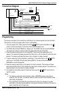
Wiring
Red Wire – Positive 12VDC power
Connect the red wire to a constant +12VDC power source.
Black Wire – Ground
Connect the black wire to the negative terminal of a 12VDC power source.
Optionally, connect to the frame of the vehicle.
Purple Wire – Positive trigger input
Connect the purple wire to a burglar or car alarm output that outputs +12V when the alarm is
triggered (the trigger signals must be at least 1 second long in order to trigger pager.)
Green Wire – Negative trigger input #1
Connect the green wire to a burglar or car alarm output that outputs ground when the alarm
is triggered (the trigger signals must be at least 1 second long in order to trigger pager.)
Blue Wire – Negative trigger input #2
Connect the blue wire to a burglar or car alarm output that outputs ground when the alarm is
triggered (the trigger signals must be at least 1 second long in order to trigger pager.)
White Wire – Fully automatic radio antenna
Connect the long white wire (female spade plug) to the power antenna wire coming from the
power antenna sensor wire.
Connect the short white wire (male spade plug) to the power antenna wire coming from the
radio switched power lead.
Warning: Do not reverse the white wire connections.
TYPE 2: CB antenna (A Position)
1. Connect the male antenna plug of an optional CB antenna into the transmitter jack marked
“ANT.”
2. Place the antenna selection switch in the “A” position.
TYPE 3: Standard radio antenna (B Position)
1. Disconnect the radio antenna lead going into the radio and connect it to the transmitter jack
marked “ANT.”
2. Connect the provided male-to-male 18” radio antenna adapter cord between the transmitter
jack marked “RADIO” and the radio antenna jack.
3. Place the antenna selection switch in the “B” position.
TYPE 4: Fully automatic radio antenna (B Position)
1. Disconnect the radio antenna lead going to the radio and connect to the transmitter jack
marked “ANT.”
2. Connect the provided male-to-male 18” radio antenna adapter cord between the transmitter
jack marked “RADIO” and the radio antenna jack.
3. Cut the power antenna lead running from the radio to the fully automatic radio antenna.
4. Connect the lead coming from the power antenna to the long white wire (marked “To power
antenna sensor wire”).
5. Connect the lead coming from the radio to the short white wire (marked “To radio switched
power lead”).
6. Place the antenna selection switch in the “B” position.