


DO NOT PLUG IN ELECTRIC CORD UNTIL
BRUSHES OR OTHER ACCESORIES HAVE
BEEN ATTACHED AND SWITCH HAS BEEN
PLACED IN THE "OFF"POSITIQN.
HANDLE,
SWITCH BOX AND CORD
.
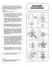
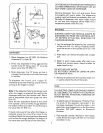
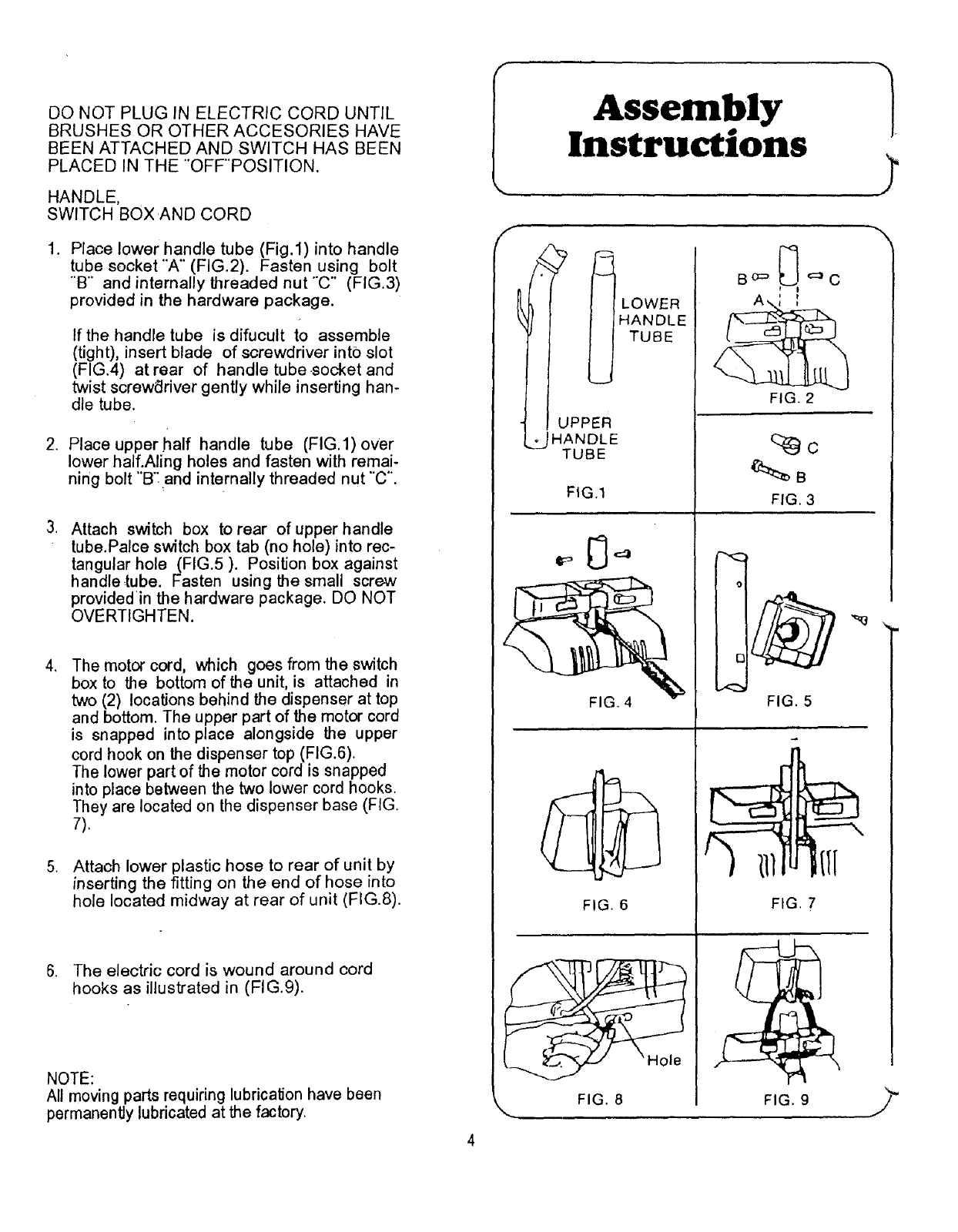
Place lower handle tube (Fig.l)into handle
tube socket"A" (FIG.2). Fasten using bolt
"'B" and internally threaded nut "C" (FIG.3)
provided in the hardware package.
If the handle tube is difucult to assemble
(tight), insert blade of screwdriver into slot
(FIG.4) at rear of handle tube socket and
twist screwdriver gently while inserting han-
dle tube.
2. Place upperhalf handle tube (FIG.l) over
lower half.Aling holes and fasten with remai-
ning bolt "B': and internally threaded nut "'C".
Attach switch box to rear of upper handle
tube.Palce switch box tab (no hole) into rec-
tangular hole (FIG.5). Position box against
handle tube. Fasten using the small screw
provided in the hardware package. DO NOT
OVERTIGHTEN.
,
.
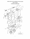
The motor cord, which goes from the switch
box to the bottom of the unit, is attached in
two (2) locations behind the dispenser at top
and bottom. The upper part of the motor cord
is snapped into place alongside the upper
cord hook on the dispenser top (FIG:6).
The lower part of the motor cord is snapped
into place between the two lower cord hooks.
They are located on the dispenser base (FIG.
7).
Attach lower plastic hose to rear of unit by
inserting the fitting on the end of hose into
hole located midway at rear of unit (FIG.8).
6. The electric cord is wound around cord
hooks as illustrated in (FIG.9).
NOTE:
All moving parts requiring lubrication have been
permanently lubricated at the factory.
Assembly
Instructions
TUBE
UPPER
_2JHANDLE
TUBE
FIG.1
FIG. 4
FIG. 6
FIG. 8
B o=" ,_ '=_ C
FIG. 2
FIG. 3
r'-,<
o
I
i E
FIG. 5
FIG. 9