


STEPS TO INSTALL YOUR WATER HEATER (Continued)
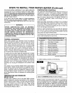
D. Open the MAIN water supply valve and the water heater CAUTION: BE SURE TO GROUND THE WATER HEATER.
will begin to fill.
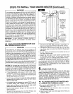
E. When the water heater has filled completely, and water
from nearby faucets runs smooth with no more air bubbles,
close the faucets.
CAUTION: Be sure to allow all air to vent from the tank.
The upper heatina element will burn out if air is trapped at
the top of the tank and the element is not covered with
water when power is turned on.
E Check your plumbing work for leaks. If any are found,
repair before doing the electrical wiring. READ THE
CAUTION NOTE FOLLOWING STEP 2 ON PAGE4.
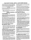
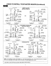
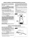
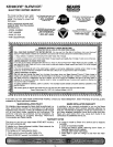
, ELECTRICAL WIRING.
Wire the water heater (240V) to the main fuse or circuit
breaker panel. Read all of the following notes, warnings and
cautions before beginning. Refer to FIG. 3A thru 3F on Pages
7 and 8.
NOTE: Remove the water heater front panel (grasp with both
hands and pull outward) and the junction box cover.
WARNING
IF YOU ARE NOT FAMILIAR WITH WIRING AND YOU
HAVEANY DOUBTS, YOU SHOULD GET HELP FROM A
LICENSED ELECTRICIAN. IF YOU DO SOMETHING
WRONG, SEVERE BURN OR SHOCK HAZARDS CAN
RESULT.
• BE SURE TO FOLLOW LOCAL AND NATIONAL CODES
AND ELECTRIC UTILITY REQUIREMENTS WHEN
MAKING THE CONNECTIONS.
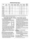
• See the specification table on Page 3 for wire and circuit
breaker or fuse size.
CAUTION: If you will use wiring from the old water heater,
and it is'aluminum, replace it with copper wiring or have a
licensed electrician make the connections.
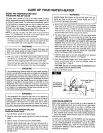
l.l[ .=:_]
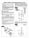
A. METAL
CONDUIT
black _red Circuit Breaker
t
/Wi HGROUND
Wa_er Heater
Junction Box _H
w_re/H _/,_FI:_ red
black _ green
Ground
Wire (bare or
green)
Rigid metal conduit (FIG.3A), between the main pane( and the
water heater junction box, with approved end fittings, is the
preferred way to ground (check codes on the use of flexible
conduit). If making a separate ground wire connection (FIG.
3B), a ground screw is provided in the water heater junction
box.
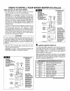
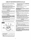
WIRING
SCHEMATIC
STANDARD
NON-SIMULTANEOUS
OPERATION
Water Heater
Junction Box
From
240V Power
Source
t
i
FOR MODEL NOS.
449.310310
449.310311
449.320310
449.320311
449.310410
449.310411
449.320410
449.320411
449.310510
449.310530
449.310531
449.320510
449.320511
Upper
Temperature
Control
Thermostat
(5PDT)
Lower
Control
Thermostat
Lower I
CAUTION: Check your model number for the correct wiring
schematic. See FIG. 3C or FIG. 3D for the proper wiring of
each model. See FIG. 3E or 3F on Page 8 for time switch or
off-peak wiring.
WIRING
SCHEMATIC
FOR MODEL NOS.
449,314410
From
240V Power
Source
t
i
L (l_ P
Junction Box
Limit Switch _ - 1
co.t,oJ r--_"_(
Thermostat ._" ! '_