


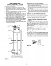
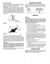

ROD AND FLOAT
SWITCH INSTALLATION
See Figure 2 for stop positions.
1. Thread float rod into float until it is firmly hand tight.
2. Slide rod guide over float rod; follow it with a rod stop
bushing (A) set about eight inches down from the top of
the rod.
3. Slide float rod up through the eye in the switch arm. Add
a rod stop bushing (B) at the top of the rod.
4. Open large loop on rod guide and mount it around the
column. Fasten with screw, making sure that the float rod
hangs vertically from the switch and moves freely in the
rod guide. Make sure the rod guide is tightly clamped.
5. Adjust rod stop bushings for designed level control.
6. Lift the rod up and down to be sure the switch will click
and that the arm does not bind on the rubber bushings.
The rod must also move freely in the guide.
7. Fill the sump and run pump through one complete cycle
to check switch operation.
Rod Sto
Switch Arm
III Ill
Rod Stop (A)
Float Rod
Sump Cover
Rod Guide
The switch unit operates as follows:
1. When the sump is dry, the float rod hangs from the switch
alan. Its weight holds the switch off.
2. When the water rises in the sump, the float lifts the svdtch
rod. The buoyancy will push the switch arm up and turn
the switch on.
3. When the water is pumped out of the sump, the float
drops down again. The weight of the float will allow the
rod and switch arm to lower and turn the drainer switch
off.
DO NOT ALLOW PUMP TO RUN DRY
Pump should not be allowed to run dry prior to shutting off.
To do so voids the warranty and could ruin the pump.
If necessary, adjust the float so this will not happen.
ELECTRICAL CONNECTIONS
Risk of electric shock. The Sump Pump
has a 3-prong electric plug. The third prong is used to
ground the pump to prevent possible fatal shock. The
third prong should never be removed. Your electrical
outlet should be the 3-prong, polarized type with an
internal ground.
Pump must be wired into a 15 amp GFCI protected individ-
ual branch circuit.
DO NOT USE AN EXTENSION CORD.
Testing for Ground
For your safety, check your outlet for ground using a Circuit
Analyzer, (Figure 3). A Circuit Analyzer will tell you by a pat-
tern of lights if the power, neutral, and ground wires are cor-
rectly connected to your outlet. It can also be used to check
other outlets in your home. A Circuit Analyzer is available in
the SEARS Electrical Department.
UL Listed
Analyzer
Outl_
Figure 3 8650194
Float
Figure 2