


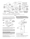
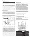
19
FIGURE 23.
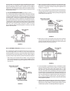
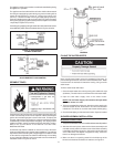
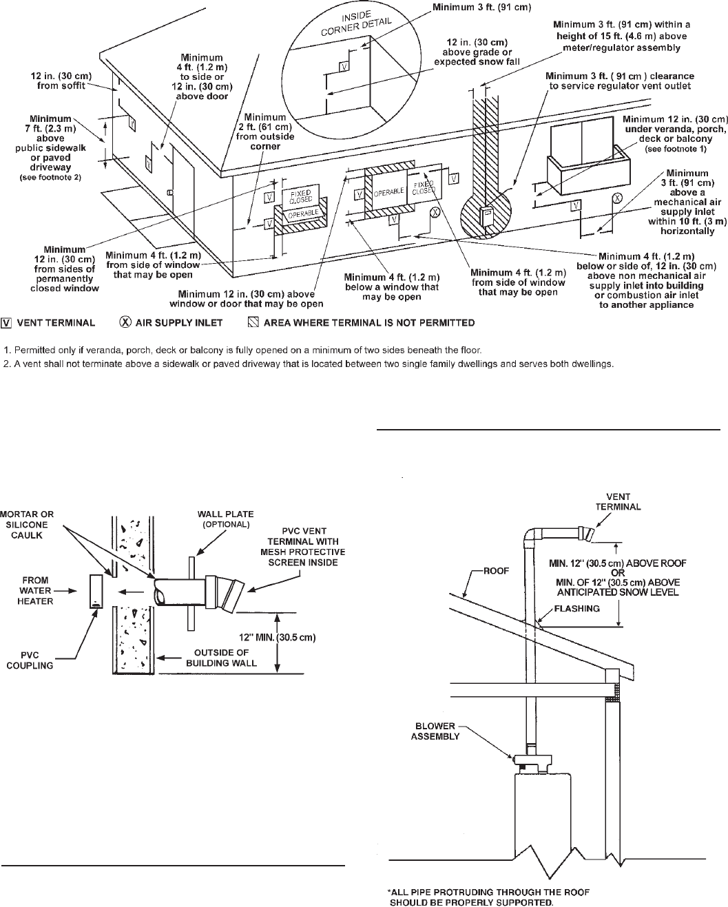
This unit can vent through 2", 3" or 4" nonmetallic pipe and fittings.
The vent pipe installation can be started from either the blower discharge
or the termination wall. Keep in mind the total vent system (pipe and
elbows) when installing the vent system, see VENTING AND
INSTALLATION AND MAXIMUM VENT LENGTHS, page 17.
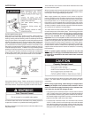
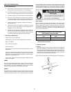
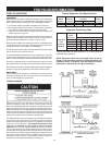
FIGURE 24.
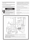
The vent terminal should be kept as close as possible to the outside
wall, but you need to allow at least 1.5" (3.8 cm) of pipe past the wall,
for the wall flange and vent terminal to mount on the pipe.
Before the vent terminal is installed, caulk (not supplied) around the pipe
on the exterior wall and install the optional wall flange. The flange can be
held to the outside wall by placing some of the caulking on the back of the
flange. The wall flange is supplied for decorative purposes only and is
not a requirement for the vent termination (if not needed by the installer).
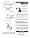
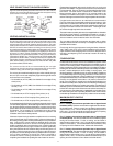
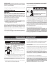
VERTICAL VENT THROUGH ROOF
This unit is approved for venting through the roof with the type vent
terminal that is included with the unit. A proper flashing or “BOOT”
should be used to seal the pipe where it exits the roof.
The total vent system should not exceed that which is specified, see
VENTING AND INSTALLATION, page 17.
All of the pipe should be secured as per the instructions in the instructions
in the VENTING AND INSTALLATION, page 17.
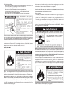
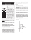
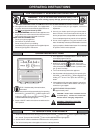
VERTICAL VENT TERMINATION RESTRICTIONS
1. Minimum of twelve 12" (30.5 cm) above the roof or twelve 12"
(30.5 cm) above the anticipated snow level. Provide proper support
for all pipe protruding through the roof.
FIGURE 25.
2. 4' (1.2 m) from or 1' (0.3 m) above any gable, dormer, or other roof
structure with access to interior of building (i.e.-vent, window etc.).
3. 3' (0.9 m) above any forced air inlet located within 10' (3.0 m).