


15
The appliance and its gas connection must be leak tested before placing
the appliance in operation.
The appliance and its individual Shut-off valve shall be disconnected
from the gas supply piping system during any pressure testing of that
system at test pressures in excess of 1/2 pound per square inch
(3.5 kPa). It shall be isolated from the gas supply piping system by
closing its individual manual Shut-off valve during any pressure testing
of the gas supply piping system at test pressures equal to or less than
1/2 pound per square inch (3.5 kPa).
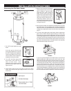
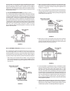
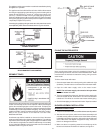
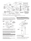
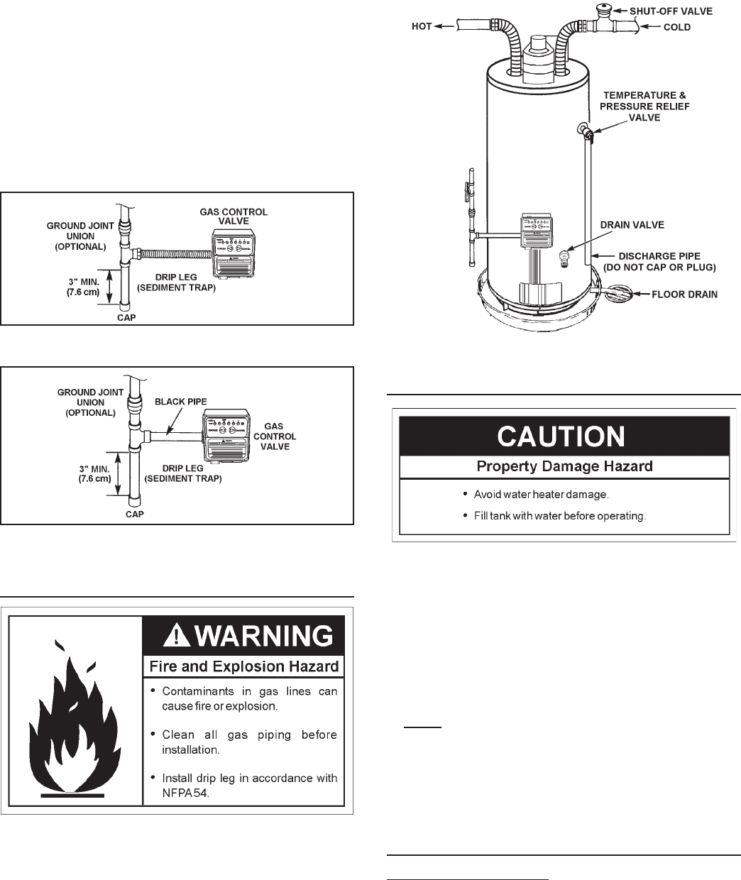
Connecting the gas piping to the gas control valve of the water heater can be
accomplished by either of the two methods shown in Figures 18 and 19.
FIGURE 18. GAS PIPING WITH
FLEXIBLE CONNECTOR.
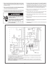
FIGURE 19. GAS PIPING WITH ALL
BLACK IRON PIPE TO GAS CONTROL.
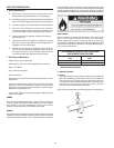
SEDIMENT TRAPS
Contaminants in the gas lines may cause improper operation of the gas
control valve that may result in fire or explosion. Before attaching the
gas line be sure that all gas pipe is clean on the inside. To trap any dirt
or foreign material in the gas supply line, a drip leg (sometimes called a
sediment trap) must be incorporated in the piping. The drip leg must be
readily accessible. Install in accordance with the “Gas Piping” section.
Refer to the current edition of the National Fuel Gas Code,
ANSI Z223.1/NFPA 54.
A sediment trap shall be installed as close to the inlet of the water
heater as practical at the time of water heater installation. The sediment
trap shall be either a tee fitting with a capped nipple in the bottom outlet
or other device recognized as an effective sediment trap. If a tee fitting
is used, it shall be installed in conformance with one of the methods of
installation shown in Figures 18 and 19.
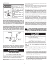
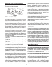
FIGURE 20.
FILLING THE WATER HEATER
Never use this water heater unless it is completely full of water. To
prevent damage to the tank, the tank must be filled with water. Water
must flow from the hot water faucet before turning “ON” gas to the
water heater.
To fill the water heater with water:
1. Close the water heater drain valve by turning the handle to the right
(clockwise). The drain valve is on the lower front of the water heater.
2. Open the cold water supply valve to the water heater.
NOTE: The cold water supply valve must be left open when
the water heater is in use.
3. To insure complete filling of the tank, allow air to exit by opening the
nearest hot water faucet. Allow water to run until a constant flow
is obtained. This will let air out of the water heater and the piping.
4. Check all water piping and connections for leaks. Repair as needed.
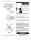
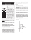
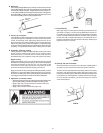
BLOWER ASSEMBLY INSTALLATION
SEQUENCE OF INSTALLATION
1. This power vented water heater comes with the blower assembly installed.
2 After the unit is set in place, make sure the blower assembly is still
mounted securely and the air intake screen of the blower assembly
is installed in the dilution air opening. Also make sure the drain port
of the rubber boot vent adapter is capped off. Lastly, make sure
there is no damage to the blower.
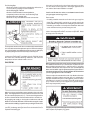
3. Make sure there is no packing material in the discharge of the
blower or the intake of the dilution air restrictor, see Figure 21.