


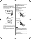
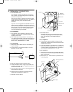
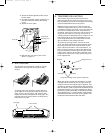
3) Attach the field-supplied conduit to the
bottom plate.
4) Connect the power supply conductors to
the Terminal block and the Grounding
screw.
5) Attach the cover plate.
6) Reinstall the front grille. (See “Front
Grille” on page 3.)
9
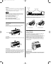
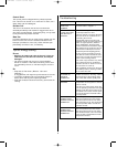
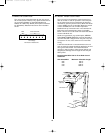
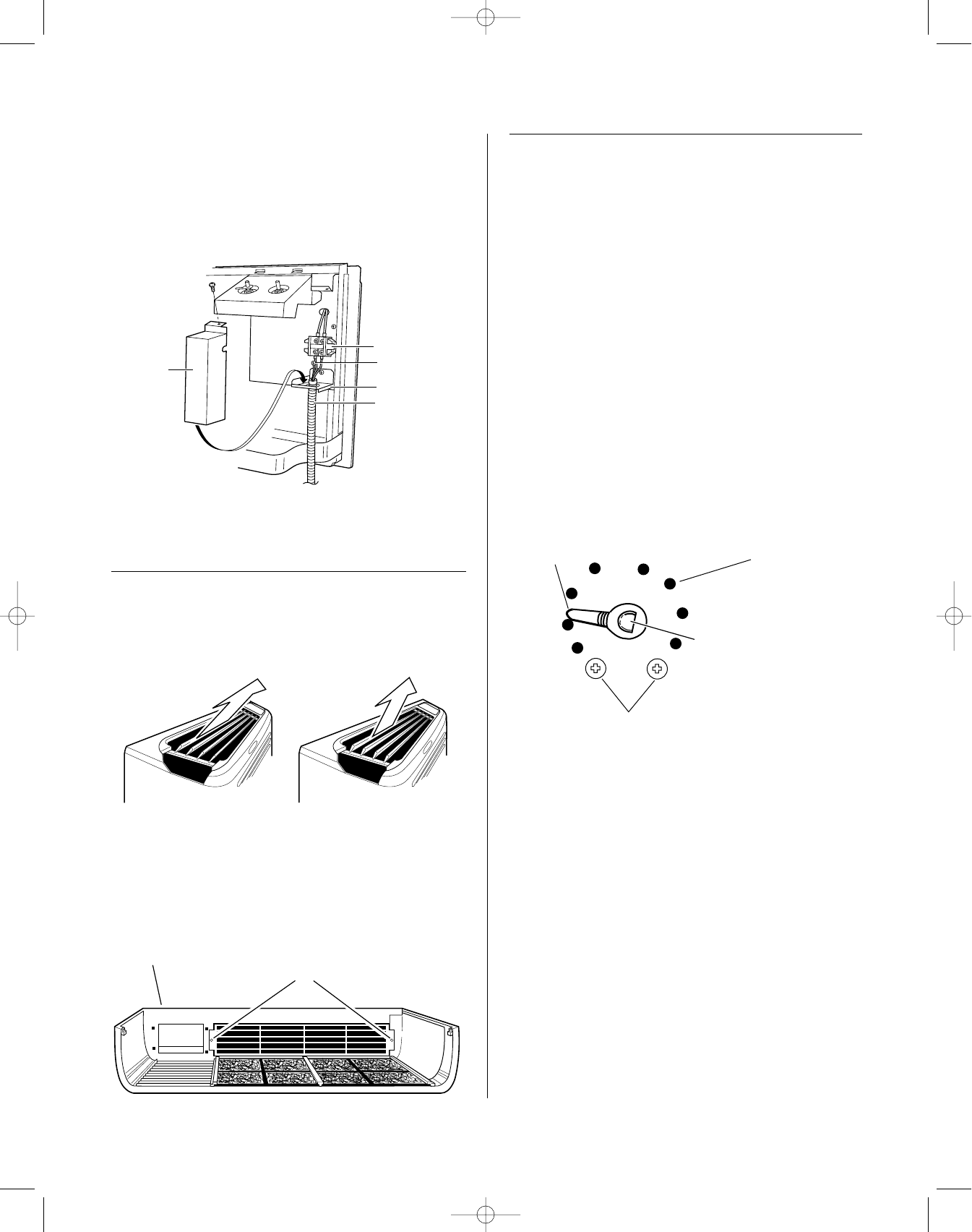
6. TEMPERATURE LIMITING
The normal range of the thermostat control is
approximately 55°F to 88°F. The control range may
be narrowed by the use of the Temperature Limiting
screws located behind the control panel.
Repositioning the screw on the left will limit the
maximum temperature about 3.7°F for each hole in
a clockwise rotation; the screw on the right will limit
the minimum temperature when moved counter-
clockwise. Limiting the maximum and minimum set-
tings prevents users from turning the controls to
extreme positions. Restrictions to full rotation of the
thermostat knob may require explanation to the
room occupant that the unit will provide comfort-
able conditions at the settings allowed.
To access the limiting screws, remove the front
grille, the thermostat knob and the operation knob
by pulling each knob off its shaft and the control
panel. (See the illustration “Fan Cycle Switch” on
page 4.) Set the limiting screws to the desired set-
ting, and replace the control panel and the control
knobs. If the settings do not allow sufficient room
temperature control, the limiting screws may have
to be repositioned.
Stop link
Tapped holes (10)
Thermostat
shaft
(Coldest)
(Warmest)
Temperature limiting screws (location at shipment)
When the limiting screws are relocated, it is recom-
mended that the screws be set no higher than the
second hole from the original bottom position. This
provides an operating range between approximately
58°F and 80°F. In order to maximize the benefit of the
temperature limiting, it may be necessary to adjust
the limiting screws seasonally, maintained at moder-
ate temperatures (i.e., heating season temperatures
limited between 60°F and 75°F; cooling season tem-
peratures limited between 85°F and 65°F).
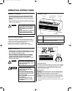
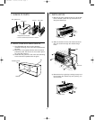
5. AIR LOUVERS
The direction of the heated or cooled air may be
adjusted by removing and turning the louvers
around.
To change the louver direction, remove the front
grille and 2 louver screws that hold the louvers in
place. Turn the louver section 180° (end for end),
replace the screws and replace the front grille. The
textured face of the louver section must be facing
toward the room side.
Front grille
Louver screws
Terminal block
Grounding screw
Bottom plate
Conduit
Cover plate
US STW PTAC 8/8/01 5:34 PM Page 9