8
4. PERMANENT CONNECTION
4-1. For 230/208V Units
The 230/208V model is equipped for connection
with a power cord according to the unit capacity
at the time of shipment.
Should local codes or special requirements speci-
fy permanent connection of this unit, use optional
adapter kit (Cover plate and Bottom plate)
STK02JB.
A power cord is supplied with 230/208V units. For
direct-connect applications, the power cord is cut
and a wire nut connection is made to the building
power supply. The cover plate and bottom plate
are the junction box kit. The conduit and wire
nuts are supplied by the installer.
4-1-1. Preparation
1) The electrical rating marked on the previously
installed air conditioner must be the same as the
supply branch circuit.
2) The modification kit provides for connection of
1/2" trade size electrical conduit and connection to
a wiring system in accordance with the National
Electric Code, ANSI/NFPA No. 70-1999.
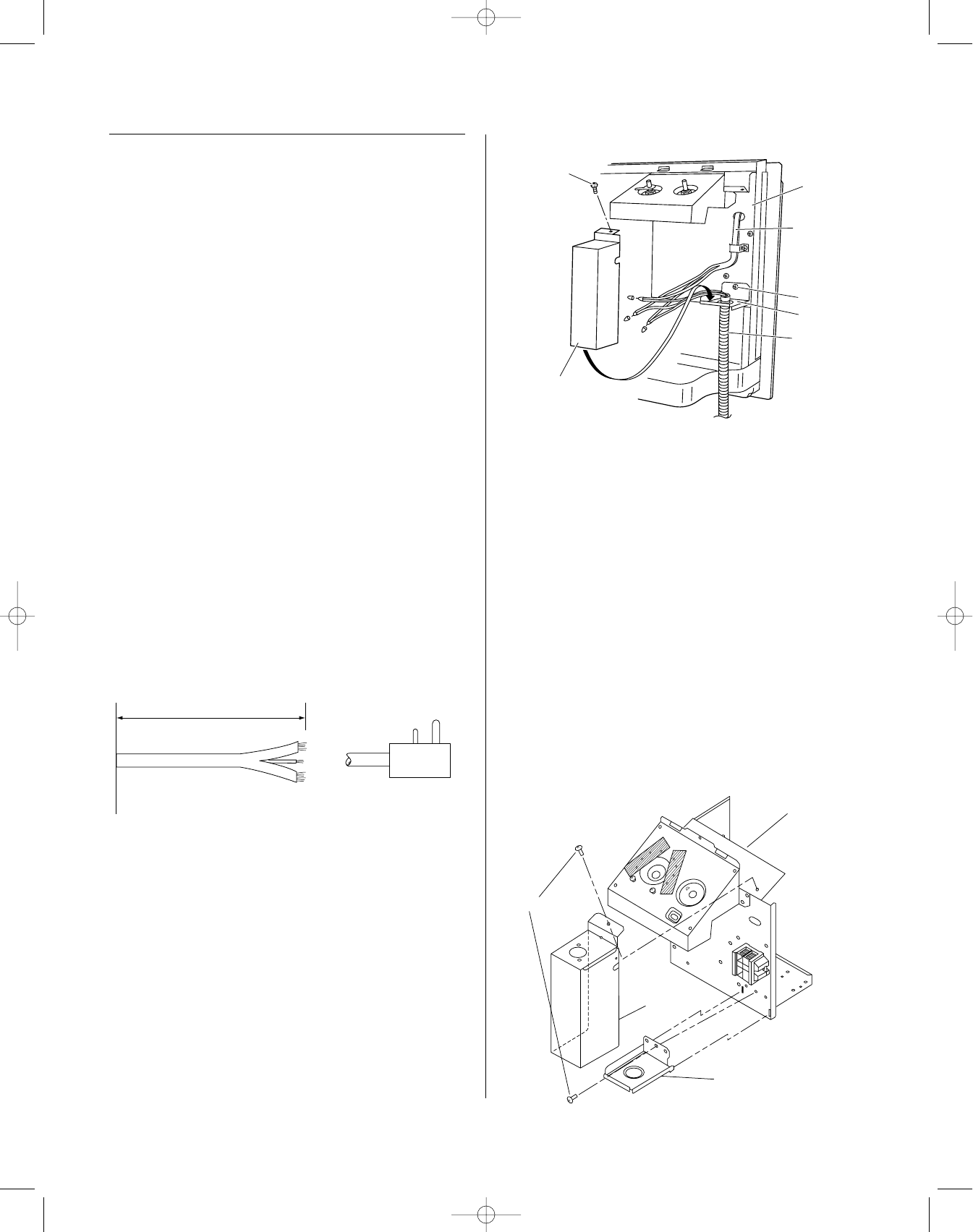
4-1-2. Installation
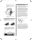
1) Remove the Front Grille from the chassis by lift-
ing out and up.
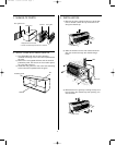
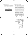
2) Cut the power cord approximately 6" from the
Electrical Junction Box.
3) Split and strip the wires as shown above.
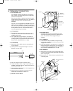
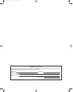
4) Install the Bottom Plate using the provided field
supplied conduit and power supply conductors to
the unit with screw “B”.
5) Connect Power Supply wires to the stripped inner
wires with the wire nuts.
6) Dress the wiring inside the compartment and
attach the cover plate with screw “A”.
7) Reinstall the Front Grille.
4-2. For 265V Units
All 265V units are direct connected and come
with the cover plate (junction box) and bottom
plate. The conduit is field-supplied by the
installer.
4-2-1. Preparation
1) The electrical rating marked on the previously
installed air conditioner must be the same as the
supply branch circuit.
2) The unit provides for connection of 1/2 trade size
electrical conduit and provision for connection to
a wiring system in accordance with the National
Electrical Code ANSI/NFPA No. 70-1993.
4-2-2. Installation
1) Remove the front grille from the chassis by lifting
out and up to clear mounting brackets. (See “Front
Grille” on page 3.)
2) Remove the “A” screw and cover plate from the
mounting plate.
Approx. 6"
Cut
Power plug
Electrical junction box
Screws
Cover plate
Bottom plate
Screw A
Electrical
junction box
Bottom plate
Screw B
Screw A
Conduit
Cover plate
Power cord
US STW PTAC 8/8/01 5:34 PM Page 8


