


9
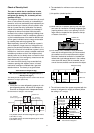
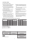
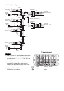
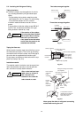
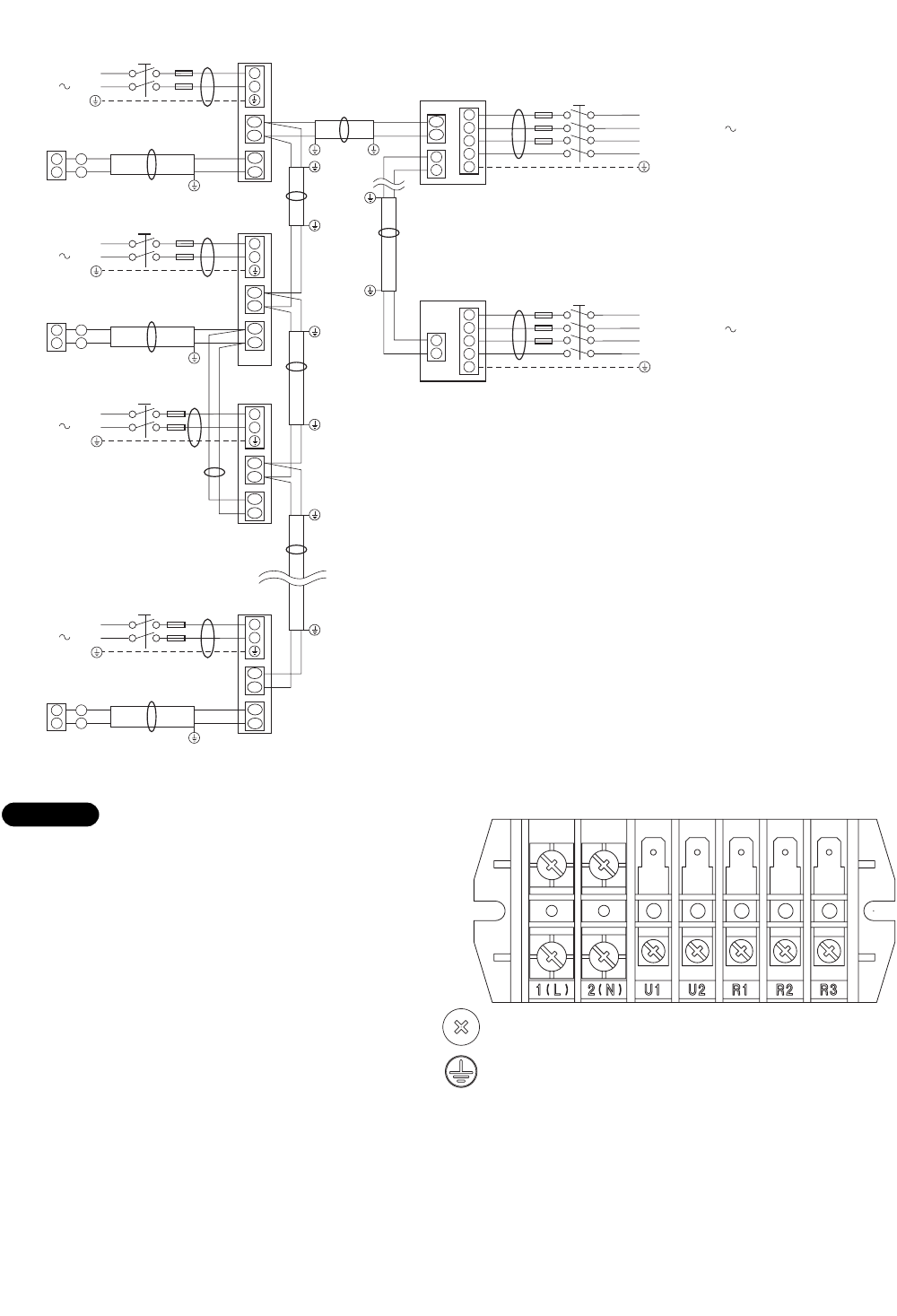
4-3. Wiring System Diagrams
U2
U1
1
2
2
1
U2
U1
4
3
3
4
5
2
1
WHT
Remote
controller
BLK
2
1
U2
U1
1
2
U2
U1
1
2
U2
U1
1
2
2
1
WHT
Remote
controller
Group control:
BLK
2
1
2
1
WHT
Remote
controller
D
A
E
Indoor
unit (No. n)
Indoor
unit (No. 1)
Indoor
unit (No. 2)
Indoor
unit (No. 3)
C
B
Outdoor unit
INV unit
L1
Power supply
L2
L3
380-415V-3N 50Hz
N
Ground
Ground
L
N
L
N
L
N
L
N
BLK
2
1
2
1
4
3
3
4
5
Outdoor unit
CS unit
Power supply
220-240V 50Hz
B
B
B
Ground
Ground
Ground
Ground
A
L1
Power supply
L2
L3
N
Ground
380-415V-3N 50Hz
Power supply
220-240V 50Hz
Power supply
220-240V 50Hz
Power supply
220-240V 50Hz
Ground
C
Ground
F
Ground
D
D
C
Ground
C
Ground
Inter-outdoor-unit control wiring
R2
R1
R2
R1
R2
R1
R2
R1
NOTE
(1) Refer to Section 5-2. “Recommended Wire Length
and Wire Diameter for Power Supply System” for
the explanation of “A,” “B,” “C,” “D,” and “E,” in the
above diagrams.
(2) The basic connection diagram of the indoor unit
shows the 7P terminal board, so the terminal
boards in your equipment may differ from the dia-
gram.
(3) Refrigerant Circuit (R.C.) address should be set
before turning the power on.
7P terminal board
1(L)
power
supply
2(N) U1 U2
Inter-unit
control
wiring
R1 R2
Remote
controller