


8
Rating Conditions: Cooling Indoor 27°C DB 19°C WB Outdoor 35°C DB 24°C WB Heating Indoor 20°C DB Outdoor 7°C DB 6°C WB
9
Rating Conditions: Cooling Indoor 27°C DB 19°C WB Outdoor 35°C DB 24°C WB Heating Indoor 20°C DB Outdoor 7°C DB 6°C WB
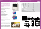
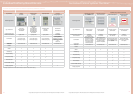
NEW 2 way gas driven VRF with electrical
power generator
SANYO’s ECO G Power is a revolution in air
conditioning design. Fitted with a permanent
magnet, non-bearing type generator, it is the rst
VRF system that can supply heating, cooling, hot
water and now also a supply of electrical power.
Each ECO G Power unit has a 4.0kW generator, which
provides enough electricity to power 8 computers or
other applications.
• Innovative technology that reduces CO
2
emissions by up to
30%
• Heat pump air conditioning system providing cooling
or heating
• Can provide both electricity and hot water in heating and
cooling mode
• Up to 4kW electricity generated
• Very ecient generator
• Hot water provided when cooling or heating when outside
ambient air temperature is above 7°C
• 22kW hot water generation capacity
• 20HP model provides 56kW cooling or 63kW heating
• Can connect to up to 36 indoor units
• 200m maximum allowable piping length (L1) (equivalent - refer
to technical manual)
• IU/OU capacity ratio 50 - 130%
ECO G Power - GHP with electricity generation
& hot water supply
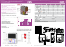
0 10 20 30 40 50 60 70 80 90 100
Air conditioning load (%)
4.5
4
3.5
3
2.5
2
1.5
1
0.5
0
Production of electricity (kW)
Production of electricity
Generates from 2kW to 4kW depending on air conditioning
load
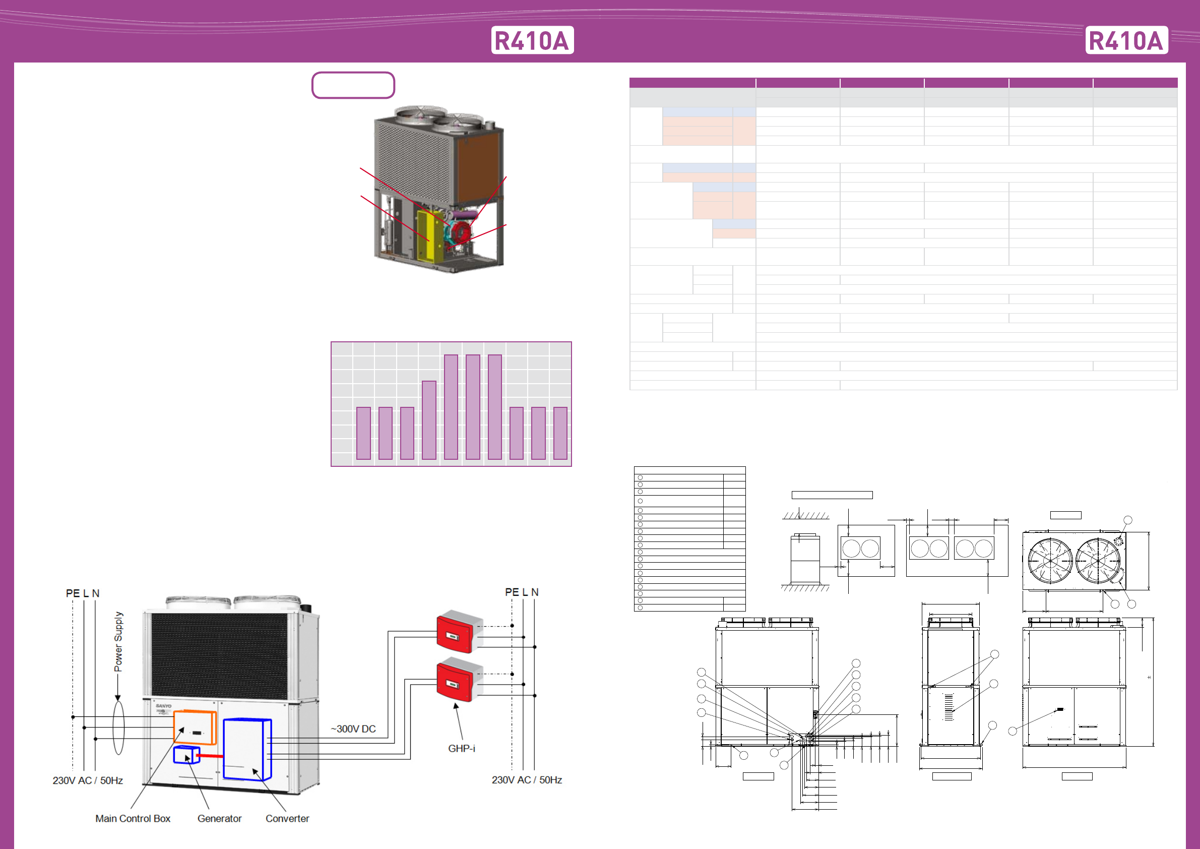
Dimensions ECO G Power
High power
engine
Line linkage
inverter
Power generator
• permanent
magnet type
• non-bearing
Double clutch
compressor
NEW
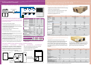
HP 20 33 36 40 45
Model
SGP-EGW190M2G2W SGP-EW120M2G2W SGP-EW150M2G2W SGP-EGW190M2G2W SGP-EGW190M2G2W
SGP-EGW190M2G2W SGP-EGW190M2G2W SGP-EGW190M2G2W SGP-EW240M2G2W
Capacity
Cooling kW 56.0 91.50 101.00 112.00 127.00
Heating STD
kW
63.0 103.0 113.00 126.00 143.00
Heating Low temp*1 67.0 109.50 120.00 134.00 142.00
Hot water 22.0 34.0 38.0 44.0 47 .00
Power generater capacity at
rating
kW DC 2.5 (Max 4.3)
Electricity
Cooling kW 1.35 2.20 2.70
Heating kW 1.01 2.02 2.55
Gas consumption
Cooling kW 44.0 (38.3)* 68.50 75.60 88.00 104.90
Heating STD
kW
48.7 (43.0)* 76.80 84.80 97.40 101.00
Heating
LOW
62.1 (56.4)* 98.90 109.40 124.20 121.30
COP Air conditioning only
Cooling 1.33 (1.41)* 1.29 1.23 1.18
Heating 1.34 (1.43)* 1.31 1.30 1.27 1.38
AVE 1.34 (1.42)* 1.30 1.25 1.28
Max COP (Inc generater, hot water)
Cooling
1.78 1.81 1.80 1.78 1.69
Height
Height
mm
2,248
Width 1,800 1,800 + 100 (Min distance) + 1,800
Depth 1,000 (+60)
Weight kg 875 1,660 1,685 1,740 1,720
Starter amperes A 30
Pipe
Gas
Inches (mm)
1 1/8 (28.58) 1 3/8 (34.92) 1 5/8 (41.27)
Liquid 5/8 (15.88) 3/4 (19.05)
Balance 3/8 (9.52)
Pipe fuel gas R3/4 (bolt, thread)
Pipe exhaust drain port mm ø25 rubber hose
Operation sound dB(A) 58 61 63
Indoor/outdoor capacity ratio 50-130%
Number of indoor connections* 32 48
Condenser actual pipe connections may vary from above pipe connections shown, please refer to technical manuals for full details.
Please refer to tube sizing charts for pipe selections and pipe length parameters.
Capacity Hot Water is available when outside ambient air temperature is above 7˚C.
Service Clearances for installation
Top View
Rear View Front View
Left Side View
at least 2000
(Units: mm)
Rear
(refrigerant tubing)
Rear
(refrigerant tubing)
at least
600
at least
600
at least
1000
at least
1000
22
50
271
54
147
207
242
275
312
461
27
83
99
138
163
178
193
555
at least
100
at least
100
1000 (external)
1800 (external)
1040
(suspension holes)
1100
(frame width)
ø736
at least
100
at least
350
400
(169)
2248 5
1014
(anchor pitch)
1000
(anchor pitch)
at least
350
Front View Front View
(Single-unit installation) (Multi-unit series installation)
Gas refrigerant pipe (Gas tube) ø28.58
Size (mm)
ø15.88
ø9.52
ø28
ø28
ø20
ø28
ø40
G: R3/4
Rp3/4
Rp3/4
OD:
Length:
1
Liquid refrigerant pipe (Liquid tube)
2
Refrigerant balance pipe (Balance tube)
3
Exhaust gas drain hose
4
Electrical power supply port
5
Inter-unit cable port
6
Inverter cable port
7
Inverter cable port
8
Fuel gas port
9
Condensation drain opening
10
Rain and condensation outlet
11
Engine exhaust outlet
12
Suspension holes 4 - ø20
13
Anchor holes 4 - ø24
14
Segment display
15
Coolant intake (top)
16
Vent
17
Hot water intake
18
Hot water outlet
19
12
14 16
9
11
17
13
15
8
3
4
2
10
1
19
18
7
5
6
Generate electricity during heating or cooling
operation
Generate electricity and air conditioning (heating or cooling)
at the same time by using remaining engine power. ECO G
Power can generate from 2.3 to 4.0kW electricity at a generation
eciency of more than 40%.