


6
Rating Conditions: Cooling Indoor 27°C DB 19°C WB Outdoor 35°C DB 24°C WB Heating Indoor 20°C DB Outdoor 7°C DB 6°C WB
7
Rating Conditions: Cooling Indoor 27°C DB 19°C WB Outdoor 35°C DB 24°C WB Heating Indoor 20°C DB Outdoor 7°C DB 6°C WB
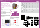
ECO G 2 Way Heat Pump VRF System
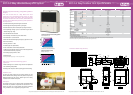
ECO G W-Multi for Heat Pump
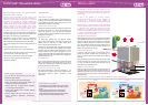
Applications
The new and improved M Series heat pump
(2 Way) not only oers improved performance
but also increased exibility. Now available as
multi-systems, many combinations are possible,
from 13HP to 50HP, allowing for more power
and enabling accurate matching of a system building
load. Additional new features include part load engine
management and compressor run hour equalisation.
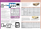
• Reduced gas consumption by Miller-cycle engine
• Reduced electrical power consumption by using DC motors
• New lightweight design by use of aluminium engine block
reduces weight by 110kg
• Part load eciencies increased
• Connectability increased - now up to 48 indoor units
• Multi-systems with combinations from 13HP up to 50HP
• 200m maximum allowable piping length (L1) (equivalent - refer
to technical manual)
• Diversity ratio 50-180%
• Extended pipe runs (total 500m)
• Industry leading sound levels
• Silent mode oers a further 2dB(A) reduction
• Chiller option
- 13HP (25kW cooling - 30kW heating)
- 25HP (56kW cooling - 67kW heating)
• 10,000 run hours between engine service intervals (equivalent
to one maintenance every 3.2 years*)
• Full heating capacity down to -20°C
• No defrost cycle
* Assuming 3120 running hrs per year - 12 hrs x 5 days x 52 weeks
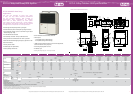
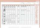
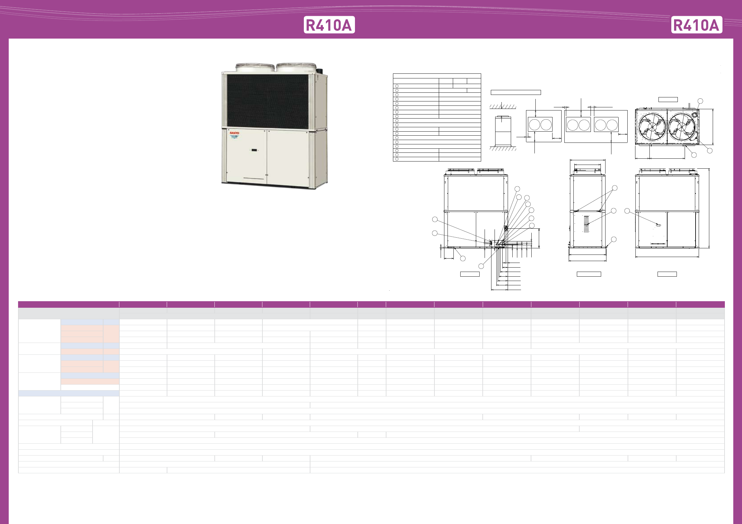
ECO G 2 Way Outdoor Unit Specications
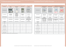
Dimensions ECO G W-Multi 2 Way
HP 13 16 20 25 26 29 32 33* 36* 40* 45* 50
Model name
SGP-EW120M2G2W SGP-EW150M2G2W SGP-EW190M2G2W SGP-EW240M2G2W SGP-EW120M2G2W SGP-EW120M2G2W SGP-EW150M2G2W SGP-EW120M2G2W SGP-EW150M2G2W SGP-EW190M2G2W SGP-EW190M2G2W SGP-EW240M2G2W
SGP-EW120M2G2W SGP-EW150M2G2W SGP-EW150M2G2W SGP-EW190M2G2W SGP-EW190M2G2W SGP-EW190M2G2W SGP-EW240M2G2W SGP-EW240M2G2W
Capacity
Cooling kW 35.50 45.00 56.00 71.00 80.50 90.00 91.50 101.00 112..0 127.00 142.00
Heating STD
kW
40.00 50.00 63.00 80.00 90.00 100.00 103.00 113.00 126.00 143.00 160.00
Heating Low temp*1 42.50 53.00 67.00 75.00 85.00 95.50 106.00 109.50 120.00 134.00 142.00 150.00
Hot water 12.00 16.00 20.00 25.00 24.00 28.00 32.00 32.00 36.00 40.00 45.00 50.00
Electricity
Cooling kW 0.85 1.35 1.70 2.20 2.70 2.20 2.70
Heating 1.01 1.54 2.02 2.55 3.08
Gas consumption
Cooling kW 24.50 31.60 38.30 60.90 49.00 56.10 63.20 62.80 69.90 76.60 99.20 121.80
Heating STD
kW
28.10 36.10 43.00 58.00 56.20 64.20 72.20 71.10 79.10 86.00 101.00 116.00
Heating LOW 36.80 47.30 56.40 64.90 73.60 84.10 94.60 93.20 103.70 112.80 121.30 129.80
COP
Cooling 1.40 1.37 1.41 1.14 1.40 1.38 1.37 1.41 1.39 1.41 1.25 1.14
Heating 1.37 1.35 1.43 1.34 1.37 1.36 1.35 1.41 1.39 1.43 1.38 1.34
AVE 1.39 1.36 1.42 1.24 1.39 1.37 1.36 1.41 1.39 1.42 1.31 1.24
Max COP (inc hot water) Cooling 1.87 1.85 1.92 1.54 1.87 1.86 1.85 1.90 1.89 1.92 1.69 1.54
Size
Height
mm
2,248
Width 1,800 1,800 + 100 (min distance) + 1,800 (in a straight installation)
Depth 1,000 (+60)
Weight kg 790 820 850 1,580 1,610 1,640 1,670 1,700
Starter amperes (A) 30
Piping connection
Gas
Inches (mm)
1 1/8 (28.58) 1 3/8 (34.92) 1 5/8 (41.27)
Liquid 1/2 (12.7) 5/8 (15.88) 3/4 (19.05)
Balance 3/8 (9.52)
Pipe fuel gas R3/4 (bolt thread)
Pipe exhaust drain ø25 rubber hose
Operation sound dB(A) 57 58 62 60 61 63 65
Indoor/outdoor capacity ratio 50-180 % 50-130 %
Number of indoor connections 32 36 48
* In case of these combinations EGW190M2G2W is able to connect as W-multi instead of EW190M2G2w.
* 1: Low temp condition: Outdoor temperature 2 C˚.
Condenser actual pipe connections may vary from above pipe connections shown, please refer to technical manuals for full details.
Please refer to tube sizing charts for pipe selections and pipe length parameters.
Capacity Hot Water is available when outside ambient air temperature is above 7C˚.
Rear View Front View
Left Side View
at least 2000
Service Clearances for installation
(Units: mm)
Rear
(refrigerant tubing)
Rear
(refrigerant tubing)
at least
600
at least
600
at least
1000
at least
1000
at least
100
at least
100
at least
100
at least
350
at least
350
Front View Front View
(Single-unit installation)
(Multi-unit series installation)
Gas refrigerant pipe (Gas tube)
ø25.4 ø28.58
ø12.7
Size (mm)
120Model Type 150
190 and 240
ø15.88
ø9.52
ø28
ø28
ø28
G: R3/4
ø20
4 - ø20
4 - ø24
Rp3/4
Rp3/4
OD: ø25 Length: 200
1
Liquid refrigerant pipe (Liquid tube)
2
Refrigerant balance pipe (Balance tube)
3
Exhaust gas drain hose
4
Electrical power supply port
5
Inter-unit cable port
6
Fuel gas port
7
Condensation drain opening
8
Rain and condensation outlet
9
Engine exhaust outlet
10
Suspension holes
11
Anchor holes
12
Segmented display
13
Coolant intake (top)
14
Vent
15
Hot water intake
16
Hot water outlet
17
Cable inlet for interlock and the like
18
Top View
1800
2248
400
1014
(anchor pitch)
1000
(anchor pitch)
10
14
12
12
1040
1000
ø736
1060
9
15
11
27
118 50
55
54
147
207
242
275
312
461
55
83
99
95
22
555
163
271
3
17
16
7
2
1
4
8
18
6
5