


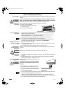
This air conditioner uses the new refrigerant R410A.
Refrigerant service valve size = 5/16"
NOTE
85264189989003 © SANYO 2007
SANYO Commercial Solutions In Canada
A Division of SANYO North America Corporation SANYO Canada Inc.
Cornerstone Business Park, 1-300 Applewood Crescent, Concord
1062 Thorndale Avenue, Ontario, L4K 5C7, Canada
Bensenville, IL 60106, U.S.A.
W
Contents
Page
IMPORTANT!
Please Read Before Starting .................................. 2
1. GENERAL .......................................................... 3
1-1. Tools Required for Installation (not supplied)
1-2. Accessories Supplied with Unit
1-3. Optional Copper Tubing Kit
1-4. Type of Copper Tube and Insulation Material
1-5. Additional Materials Required for Installation
2. INSTALLATION SITE SELECTION ................... 4
2-1. Indoor Unit
2-2. Outdoor Unit
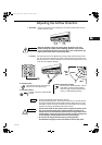
3. HOW TO INSTALL THE INDOOR UNIT ............. 6
3-1. Remove the Rear Panel from the Unit
3-2. Make a Hole
3-3. Install the Rear Panel on the Wall
3-4. Remove the Grille to Install the Indoor Unit
3-5. Shape the Indoor Side Tubing
3-6. Wiring Instructions
3-7. Recommended Wire Length and Diameter
3-8. Wiring Instructions for Inter-unit Connections
3-9. Mounting
3-10. Drain Hose
4. HOW TO INSTALL THE OUTDOOR UNIT ....... 16
4-1. Wiring Instructions for the Outdoor Unit
5. REFRIGERANT TUBING .................................. 17
5-1. Use of the Flaring Method
5-2. Flaring Procedure with a Flare Tool
5-3. Caution before Connecting Tubes Tightly
5-4. Connecting Tubing between Indoor and
Outdoor Units
5-5. Insulation of Refrigerant Tubing
5-6. Taping the Tubes
5-7. Finishing the Installation
6. AIR PURGING................................................... 19
■ Air Purging with a Vacuum Pump (for Test Run)
■ Basic Functions of the Service Valves
■ Pump Down
INSTALLATION INSTRUCTIONS
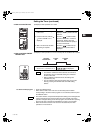
Model Combinations
Combine indoor and outdoor units only as listed
below.
Indoor Unit Outdoor Unit
KHS1872 CH1872
KHS2472 CH2472
Power Source:
60 Hz, single-phase, 230/208 V
– Inverter Split System Air Conditioner –
COOL/DRY/HEAT Model
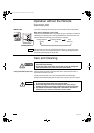
Be sure to read the yellow instruction sheet
attached to the outdoor unit for models using the
new refrigerant R410A.
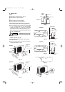
The illustrations are based on the typical appearance of
a standard model. Consequently, the shape may differ
from that of the air conditioner that you are installing.
NOTE
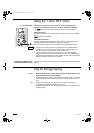
7. REMOTE CONTROL UNIT INSTALLATION
POSITION ......................................................... 23
7-1. Mounting on a Wall
8. ADDRESS SWITCH .......................................... 24
8-1. Address Setting of the Remote
Control Unit
07-153 CH1872-2472 6/12/07 3:14 PM Page a