


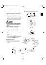

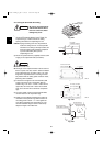
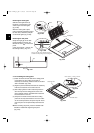
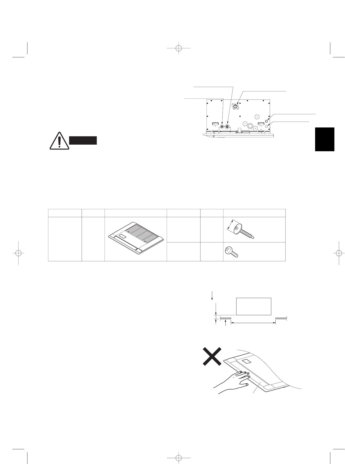
Refrigerant tubing joint
(gas tube)
Refrigerant tubing joint
(liquid tube)
Drain pipe connection
(Be sure to connect the
supplied flexible hose.)
Inter-unit Control Wiring
Power supply outlet
35
A
Fig. 3-46
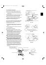
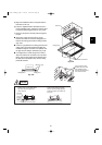
● Route the power wiring into the indoor unit through the power inlet on the side of the unit. At this time, be
sure that the wiring passes through the power inlet in the unit power section. If the wiring does not pass
through this inlet, it may become pinched by the ceiling panel, and may result in fire.
● Pass the wiring through the power inlet on the electrical component box and connect it to the terminal plate.
Then fasten the wiring in place with the clamp.
WARNING
3-12. Electrical Power Wiring
(1) Wiring connections
The power inlet is on the side of the indoor unit where the
refrigerant tubing is located. The electrical component box
is on the lower air intake surface of the indoor unit.
(Fig. 3-46)
(2) Wiring
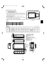
3-13. How to Install the Ceiling Panel
For fastening
side panel
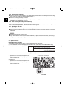
Part name Quantity Appearance Part name Quantity Appearance
Component Parts
ø11/16
"
Ceiling panel
Screw
M5 × 40
or
5/16" × 9/16"
Washer-head
screw
1
2
4
4 × 12 or 5/32" × 15/32"
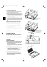
3-13-1. Before Installing the Ceiling Panel
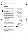
Checking the position of the indoor unit
(1) Check that the dimensions of the ceiling opening are
the following:
28-47/64" × 23-17/64"
* For details, refer to the installation manual that was
supplied with the indoor unit.
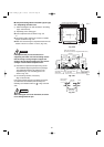
(2) Check that the positions of the ceiling surface and
indoor unit are as shown in Fig. 3-47. If the positions
of the ceiling surface and indoor unit are not correct,
problems such as air leakage, water leakage, and flap
operation trouble may occur.
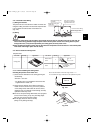
● Do not rest the panel facing downwards, lean up against
a wall, or leave it sitting on top of a protruding object.
Doing so may scratch the panel surface.
● Do not apply excessive force to the flap.
(Doing so may damage the flap.)
Indoor unit
Ceiling opening dimension
25/32 – 1 in.
Ceiling surface
Fig. 3-47
Be sure that this distance is within the range of 25/32 – 1 in.
If it is not within this range, malfunction or other problems may result.
Flap
Fig. 3-48
07-007 W-2WAY_II_NA 1/23/07 6:09 PM Page 35