13
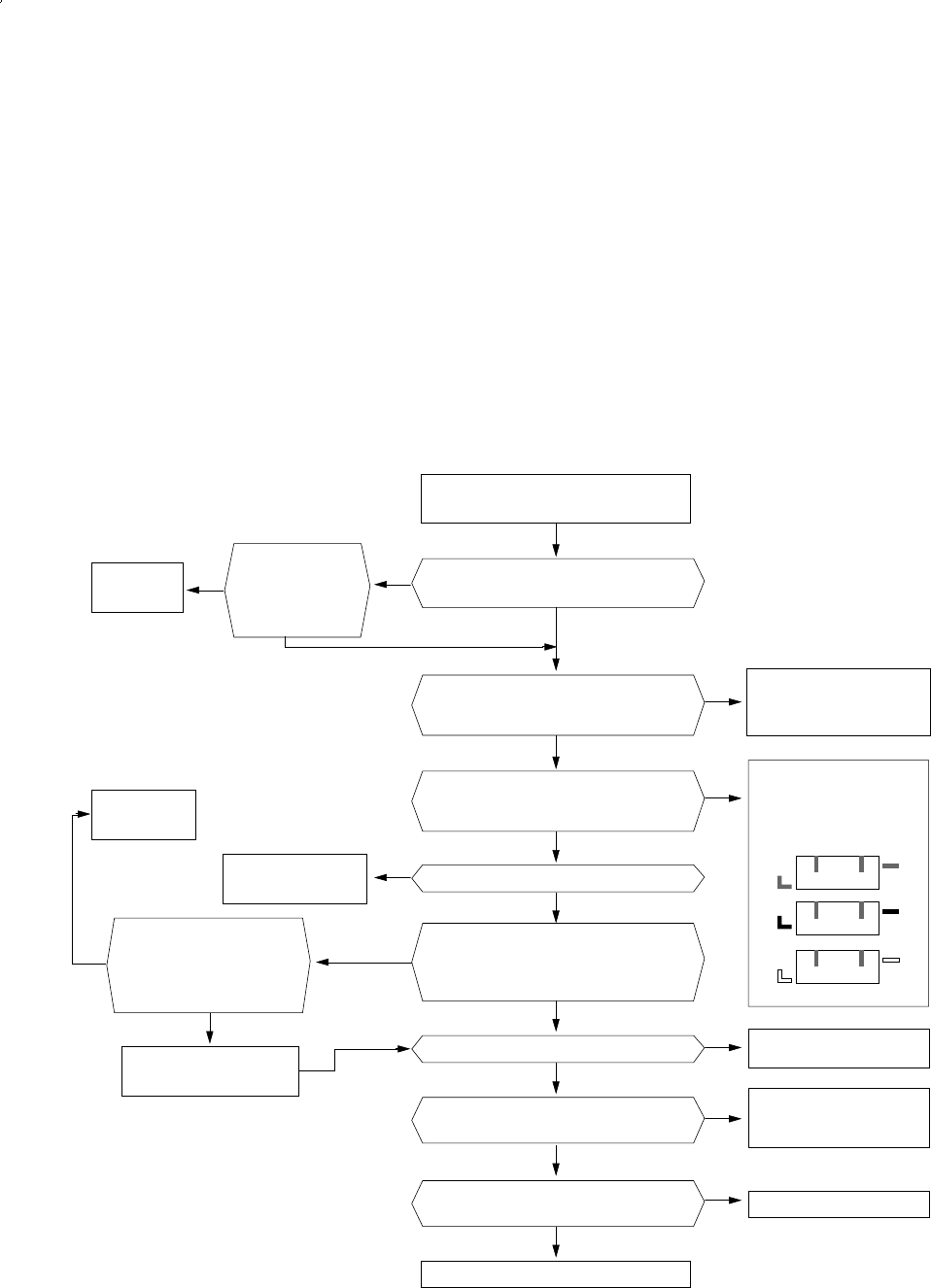
3-3-3 No Power (Outdoor unit)
1) Inspection items
(1) Á Is the power source normal (The rating Voltage ±10% range)?
(2) Is the outdoor power connected normally? ((1) of terminal : L, (2) of terminal : N,
(3) of terminal : communication) ?
(3) Check whether the display of outdoor PCB(SEG1) is shown in the order of A- B - C when the
power is applied.
If the display (SEG 1) is not shown the inspection and repair shall be performed in the sequence
of the following:
2) Inspection sequence
Normal of
outdoor PCB
Replace the fuse
(F701) 250V 3.15A.
Replace the
transformer
Assemble the transformer
in the normal way.
Put the power off and put it on after
5 seconds.
Replace the outdoor unit Ass'y main PCB.
Reinstall the power cord and
communication line with the
reference of installation manual.
Replace the fuse F101
(250V 2 A).
Replace the IC 02 (KA7805)
Check and Replace the rectifying
diode of power side
(D101 - D104) and KA 7812.
After watching the display of
PCB board, assemble the
color and shape of housing
correctly as follows:
Is the display of PCB shown in the
sequence of A-B-C?
Check the
communication of
PCB and whether
the LED 1 is contin-
uously flickering.
Are the power cord ((1) L, (2) N) and
communication line (3) of outdoor terminal
block connected correctly?
Is the terminal of PCB terminal (RY71, 72, 73)
are assembled in the correct position?
Is the fuse open? (F701)
Is the fuse (F101, 250V 2 A) blown out?
Check whether the output voltage of
IC01 (KA 7812) is DC 12V.
Check whether the output voltage of
IC02 (KA 7805) is DC 5V.
Insert the primary side of power transformer
in the terminal GT01 and then is the voltage
of secondary side normal? (AC 15V- AC 25V)
Measurement of resistance
of power transformer
Are they as follows?
1st side 190 ~ 210Ω
2nd side 0.9 ~ 1.1Ω
BLK
WHT
BLK
RED
RED
WHT
YES YES
NO
NO
YES
YES
NO
YES
NO
YES
NO NO
YES
YES
YES
NO
NO
YES
NO
NO
DB98_05645A(1)_1 5/30/02 7:04 PM Page 13


