GB
2. COMPONENTS
(See Fig.
11
11
1)
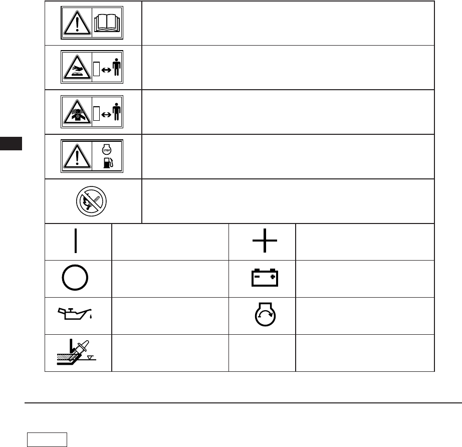
SYMBOLS
q Plug (drain)
w Suction
e Delivery
r Plug (priming)
t Handle
y Spark plug cover
u Spark plug
i Air cleaner
o Carburetor
!0 Primer button
!1 Tank cap
!2 Fuel tank
!3 Casing cover
!4 Speed control lever
!5 Stop Switch
!6 Set base
!7 Oil filler (with oil gauge)
!8 Recoil starter
!9 Starter handle
@0 Choke lever
@1 Muffler
@2 Strainer
@3 Hose coupling
@4 Hose band
@5 Tools
@6 Instruction for use
(This publication)
NOTE Please refer to the illustrations on the back page of the front
cover or back cover for Fig.
1 1
1 1
1 to
88
88
8 indicated in the sentence.
.launams'renwoehtdaeR
.ecafrustohehtforaelcyatS
.suonosiopsisagtsuahxE
.aeradetalitnevnunanietarepotonoD
.gnileufererofebenigneehtpotS
.detibihorpgnikomsdnaemalfnepo,eriF
)nuR(nOytiralopevitisoP;sulP
)potS(ffOyrettaB
lioenignE)tratscirtcelE(tratsenignE
lioddA
2003.10.30, 6:50 PMPage 4


