


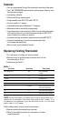
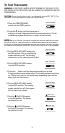
Figure 3
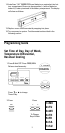
7. Drill the marked holes using a 3/16” drill bit.
8. Tap plastic anchors into the holes.
9. Align base with plastic anchors and feed wires through opening.
See Fig 4.
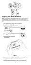
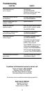
Figure 4
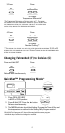
10. Secure base to wall with supplied screws.
11. Connect wires to terminal strip. Refer to wiring diagrams on other
side of this sheet. Make sure wire connections are secure.
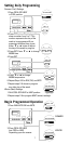
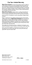
12. Place fan option switch into either the “ELEC” or “GAS” position
depending upon the type of furnace. Refer to Figure 5.
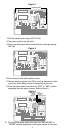
Figure 5
13. Put heat pump option switch into either the “NON HPUMP” or
“HPUMP” position, depending on the type of system in the home.
4
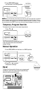
MOUNTING HOLES
FAN
OPERATION
SWITCH
Controls fan delay
HEAT PUMP
SWITCH
Controls
heat pump