


SECTION 5: PUMP INSTALLATION
11
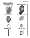
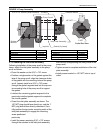
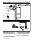
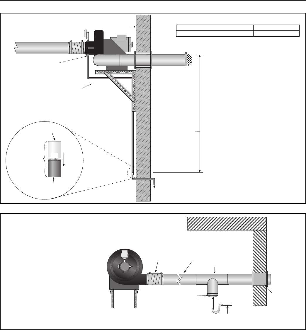
FIGURE 9: Condensate Check Valve
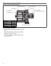
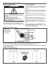
FIGURE 10: Condensate Tee - Discharge Side
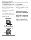
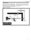
5.3 Condensate Trap and Condensate Tee
The condensate trap assembly (optional) (P/N
01327001), should be installed on the inlet side of
the EP-200 Series pump assembly, See Page 11,
Figure 9.
It is possible to eliminate the condensate trap assem-
bly on the pump if the one-inch threaded hole is
plugged. This arrangement will permit drainage of
condensate through the pump and outside via hori-
zontal (pitched) discharge line.
The condensate trap assembly in the discharge line
can be eliminated if the discharge line is horizontal
through the wall and pitched down at least one inch
per foot. A condensate trap on the discharge side is
required if there is a vertical rise in the discharge
line.
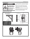
Wall
1" NPT threaded hole.
Use 1" x ¾" reducer.
(not supplied)
Must be connected
to a drain system
in accordance with
local codes.
flow
Condensate
Valve
Assembly
3/4" female
3/4" female
36" Minimum
vertical drop
between pump
and condensate
valve assembly.
Copper or
galvanized pipe
between pump
and condensate
valve.
Description Part Number
Condensate Valve Assembly 01327001
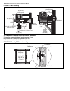
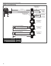
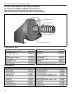
Approved
Thimble
(if applicable)
Flex Boot
4"(100 mm)
Minimum
1"(25 mm)
P.V.C
Tee
Drain Cap