


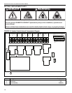


SECTION 4: TYPICAL EXTERNAL WIRING DIAGRAMS
9
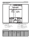
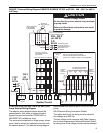
FIGURE 7: External Wiring Diagram ROBERTS GORDON
®
EP-203 or EP-303, 208 - 230 V (or 460 V)
3 Ø Pump
4.3 EP-203 or EP-303 208 - 230 V (or 460 V) 3 Ø
Pump External Wiring Diagram
The external wiring diagram above shows the
connections for four zones of system burners.
System burners can be either CORAYVAC
®
or
VANTAGE
®
NP (multiburner only).
The zones are connected to a single pump, unless
zone 3 and/or zone 4 are selected to function with
the optional pump 2. The external wiring diagram
above shows connection to an EP-203 or EP-303 3 Ø
pump.
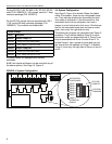
4.3.1 External Wiring Connection Details
The cable used for all the wiring must be rated for
line voltage up to 600 Vac.
The low voltage circuit conforms with Class 2 separa-
tion of circuit requirements. National Electrical Codes
®
for wiring class 2 low voltage circuits must be followed.
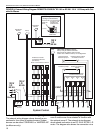
System Control
R R R R PS 2PS 124 VAC
COM
24 VAC
COM
PS 1 PS 2WWWW
24 VAC
120 V
1 Ø
60 Hz
Ground
G
L
N
120 V
1 Ø
60 Hz
PUMP 2PUMP 1
POWER
SUPPLY
N
L
Z1
Z2
Z3 Z4
N
N
N
NLL
L
L
All burners must be
connected to Ground
(Not shown)
Zone 1
Zone 2 Zone 3 Zone 4
EP-203 or
EP-303 3 Ø
Pump
N
L
L
N
208 - 230 V
(or 460 V)
3 Ø
60 Hz
Individual supply
for pump rated for
total full load current.
See Section 2.3
for details.
EP-203 or
EP- 303 3 Ø Pump
M
L1
L3
L2
The power supply for the
pump must be separate
from the controller supply
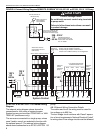
TWO PUMP SYSTEM (optional)
Pump 1 may be used for all zones.
Pump 2 may be used to control zone 3
and/or zone 4. Refer to Pump 1 for configuration.
Low voltage thermostats
located in heated zone
Zone
1
Zone
2
Zone
4
Zone
3
Pressure
switch
located at
pump 2
Pressure
switch
located at
pump 1
Motor Contactors
P/N 10050011
P/N 10050012
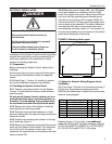
CAUTION
Product Damage Hazard
Do not directly connect control relay terminals
to pump motor
.
Failure to follow these instructions can result
in product damage.