


SYSTEM CONTROL INSTALLATION, OPERATION AND SERVICE MANUAL
6
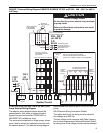
For the EP-203 (3 Ø), EP-303 (3 Ø), EP-100, EP-201
and EP-301 208/230 V (1 Ø) pumps, use the 17 Amp
contactor package (P/N 10050011).
For the EP-301 pumps that are operated with 120 V
(1 Ø) use the 28 Amp contactor package (P/N
10050012). The contents are listed below:
All pump motors are equipped with thermal
overloads.
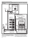
3.3.3 If an ou tside air blower is to be used with any of
the above options, See Page 10, Figure 8.
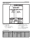
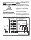
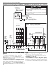
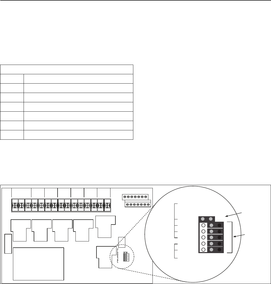
3.4 System Configuration
See Page 6, Figure 4 for details. Below the ribbon
cable J2 connector, there are six configurable jump-
ers. They indicate whether the thermostat for each
zone uses an anticipator. If the thermostat for that
associated zone has an anticipator, then use a
jumper to cover both pins for that zone. If the thermo-
stat for the associated zone does not use an antici-
pator, then cover the right side pin only.
The bottom two jumpers are associated with Pump 2
operation. They indicate whether Pump 2 is active
and which zones are associated with it. Pump 2 can
only be associated w
ith Zone 3 and/or Zone 4. To
enable Pump 2, use a jumper to cover both pins for
the zone(s) that will operate on Pump 2. To disable
Pump 2, cover only the right side of the pin of zone 3
and 4.
FIGURE 4: System Configuration
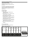
Contactor Packages
Part No.
Description
10050011 Contactor Package 17A
10001002 Enclosure IEC metal 8X6X6 NEMA 1
90600200 CONT 208-600 17A (A16-30-10-84)
10050012 Contactor Package 28A
10001002 Enclosure IEC metal 8X6X6 NEMA 1
90600205 CONT 208-600 28A (A26-30-10-84)
G N L N L N L N L N L N L N L
AC POWER IN
PUMP 1 ZONE 1 PUMP 2ZONE 2 ZONE 3 ZONE 4
24 VAC
COM
Z1W
Z2W
Z3W
Z4W
24 VAC
COM
Z1R
Z2R
Z3R
Z4R
AIR
SW1
AIR
SW2
AIR
SW1
AIR
SW2
ANTICIPATOR
LOAD ENABLE
ZONE 1
ZONE 2
ZONE 3
ZONE 4
ZONE 3
ZONE 4
PUMP 2
OPERATION
ENABLE
ANTICIPATOR
LOAD ENABLE
ZONE 1
ZONE 2
ZONE 3
ZONE 4
ZONE 3
ZONE 4
PUMP 2
OPERATION
ENABLE
FEATURE
ENABLED
FEATURE
DISABLED