


DUALAIR
®
HEATING AND COOLING UNITS INSTALLATION OPERATION AND SERVICE MANUAL
26
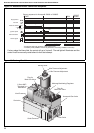
12.3.3 Burner Lockout Reset Button
The red warning light will illuminate when the control
has gone to lockout. This may be caused by flame
failure. Press the reset button,(See Page 5, Section
4.1), or the remote reset if installed on site.
12.4 Cooling Section Operation
The temperature control will bring on the fan to
operate the DualAir
®
unit in cooling mode dependent
on the current temperature and set point.
Once the temperature rises above the set point,
there are three stages of cooling available
dependant on site installation.
Cooling Stage 1 (optional free cooling):
The fan runs and change over dampers (if fitted)
allow fresh air to be drawn from outside.
If the temperature continues to rise then
Cooling Stage 2 operates: The fan runs, the
dampers (if fitted) return to recirculating air and the
first condenser operates to provide cooling at half
load.
Should the temperature continue to rise,
Cooling Stage 3 operates: The fan runs, the
dampers (if fitted) remain in recirculating air and the
second condenser operates to provide cooling at full
load.
12.4.1 Filters
Air cleaning filters are fitted to the DualAir
®
unit to
protect the cooling coil and provide improved
environmental conditions.
The filters will require to be replaced at least three
times per year and in dirty environments cleaning of
the filters may be required at more frequent
intervals.
When the filters are dirty the warning light will show
see Page 25, Section 12.2.1. The filters must be
cleaned or replaced immediately.
Do not operate the DualAir
®
unit without filters
as the cooling coil may become blocked and
impossible to clean.
12.5 Heating Section Lighting Instructions
12.5.1 To Turn On Heater
1. Ensure that the electrical and gas supplies to
the heater are on. Check that the on site con-
trols are “ON”.
NOTE: The thermostat setting must be above the
ambient temperature for the heater to operate.
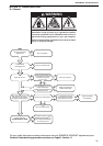
2. The green light will be on and the automatic fir-
ing sequence will begin as described on Page
22, Figure 12. The heater will now operate
automatically under the control of the on site
controls. Following long shut down periods, the
control may go to lockout. See Page 26, Sec-
tion 12.3.3.
12.5.2 To Turn the Heater Off
Set the installed remote controls to “OFF”.
The burner will turn off immediately.
The fan will continue to run for a few minutes.
To restart turn the control used above to “ON”.
12.6 Simple Fault Finding
Possible reasons for the heater not operating are:
1. Gas supply not turned ON.
2. Electricity supply not turned ON.
3. The time and/or temperature controls are not
“ON”.
4. One or both of the limit thermostats may have
operated. This may be caused by an interrup-
tion of the electrical supply or failure of the
distribution fan.
If the limit thermostats persistently operate, there is
a fault which must be investigated by a contractor
qualified in the installation and service of gas-fired
heating equipment.
12.6.1 Simple Fault Finding (burner faults)
If the burner fails to ignite for any reason, it will go to
lockout. This will be indicated by the red light on the
heater or at the remote indicator (if fitted).
1. Press in and release the lockout reset button. If
a remote reset is not fitted a reset button is on
the side panel of the heater. See Page 5, Sec-
tion 4.1.
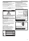
WARNING
Explosion Hazard
If control locks out, do not make more than 3
attempts to restart the heater.
Dangerous gas mixtures can build up.
The fault must be traced and repaired by a
registered installer or service engineer.
Failure to follow these instructions can result in
death, injury or property damage.