


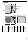

SECTION 6: FLUE INSTALLATION
9
SECTION 6: FLUE INSTALLATION
6.1 Changing Flue and Air Intake Orientation
The heater is sold with horizontal flue and fresh air
connections as standard. If vertical flue and fresh air
connections are required, follow the instructions on
Page 29, Section 15.4.
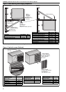
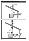
6.2 Flue Installation
The flue must terminate outside of the building.
Flues and air intakes must be a fully sealed system
and correctly sized for the model. Flues should be
assembled as detailed on Page 9, Figure 5 through
Page 10, Figure 7. The joints between the flue
terminal and the roof or wall must be properly
sealed. If the flue passes through a wall or ceiling of
combustible material it must be enclosed by a
sleeve of non-combustible material and be
separated from the sleeve by at least a 25 mm air
gap.
Flues and air intakes must be adequately
supported so that the heater does not bear the
weight of the pipes.
For flue termination See Page 9, Figure 5 through
Page 10, Figure 7.
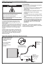
6.3 Type C
12
, C
32
& C
62
Appliance
Room Sealed.
The heaters are designed to be installed as room
sealed appliances. The flue and air intake are run as
separate pipes to the special concentric wall or roof
terminal. See Page 10, Figure 7. The wire mesh
inside the fresh air adapter on the heater must be
removed prior to installation.
6.4 Type B
22
Appliance
The flue must be fitted with a low resistance
terminal. See Page 9, Figure 5 through Page 10,
Figure 6.
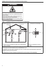
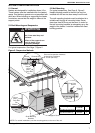
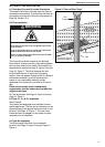
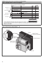
Figure 5: Flue and Roof Detail
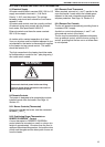
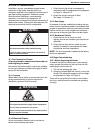
WARNING
Fire Hazard
Some objects will catch fire or explode when placed
close to heater.
Keep all flammable objects, liquids and vapours the
required distance away from the heater.
Failure to follow these instructions can result in death,
injury or property damage.
Roof
Flue
Terminal
Metal Sleeve
Masterflash
Soaker Flashing
or Rain Collar.
Flue
25 mm Air Gap to
Combustible Material