


CRV-SERIES DESIGN MANUAL
12
SECTION 5: FLOW LOADING
The patented CRV-Series burner system allows a
number of burners to be installed in-series, in the
same radiant tube, resulting in a long, continuous radi-
ant emitting surface to give even heat distribution
within the building.
To enable the burners to be correctly located within the
system, to maintain system operating vacuum and
obtain design flue gas temperatures at the pump, the
design layout is based on a simplified flow principle
using a “flow unit.”
The flow unit is defined as the amount of fuel/air mix-
ture for a heat input of 10,000 (Btu/h). This corre-
sponds to a flow rate of 1.83 cfm at 65-70°F.
For the purpose of design, flow units enter the CRV-
Series system in one of two ways:
• Through the burner.
• Through the end vent plate.
Flow units exit the system as spent produ
cts of com-
bustion via the pump.
The purpose of the end vent air is to dilute the hot
combustion gases at the burner, thereby promoting
uniform heating of the tube while avoiding excessive
heating of the combustion chamber.
For the end burner, the burner inlet flow consists of the
end vent air and combustion air. For all other
burners, the burner inlet flow consists the of the total of
the end vent air plus the combustion gases from all
upstream burners.
The requirement for minimum burner inlet flow is met if
the total flow units entering the combustion chamber
meets or exceeds the minimum as shown on Page 12,
Table 1.
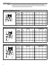
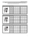
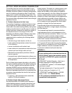
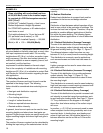
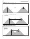
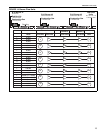
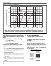
5.1 Radiant Branch Flow
The flow in a radiant branch consists of the end vent
flow units plus the flow units of combustion air from all
burners. Page 13, Figure 14 shows a representation
of flow
units for various types of branches.
The limiting factor for maximum flow in the radiant sec-
tion has been determined experimentally in terms of
the maximum burner inlet flow units that can be toler-
ated without degradation of combustion characteris-
tics at the last downstream burner. If more than the
maximum number of burners are installed per radiant
branch, the vacuum loss across the additional burners
will increase appreciably.
This maximum flow in the radiant branch can be
expressed for each burner firing rate by either a maxi-
mum number of burners per branch or the maximum
number of flow units. See Page 12, Table 1.
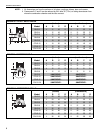
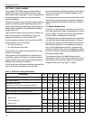
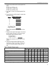
Table 1: CORAYVAC
®
Design Parameters
* CRV B-9 requires first downstream tube from burner to be aluminized heat-treated.
Burner Model B-2 B-4 B-6 B-8 B-9* B-10 B-12A B-12
Input (Btu/h) x (1000) 20 40 60 80 90 100 110 120
Flow Units per Burner 2 4 6 8 9 10 12 12
Flow Units per End Vent
(minimum flow units entering combustion chamber)
6 10152015202020
Maximum Number of Burners per Branch 6 4 4 4 2 4 3 3
Maximum Number of Flow Units per Branch 18 26 39 52 33 60 56 56
Radiant Tube Length (average distance between burners)
Minimum (ft) 10 12.5 20 20 20 30 35 35
Recommended (ft) 15 20 25 30 30 40 50 50
Maximum (ft) 20 25 35 45 50 60 70 70
Minimum Distance from Burner to Downstream Elbow (ft) 5 5 10 10 10 15 15 15
Suggested Minimum mounting Height (ft) 8 8 8 10 10 15 15 15