


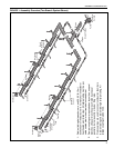
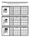
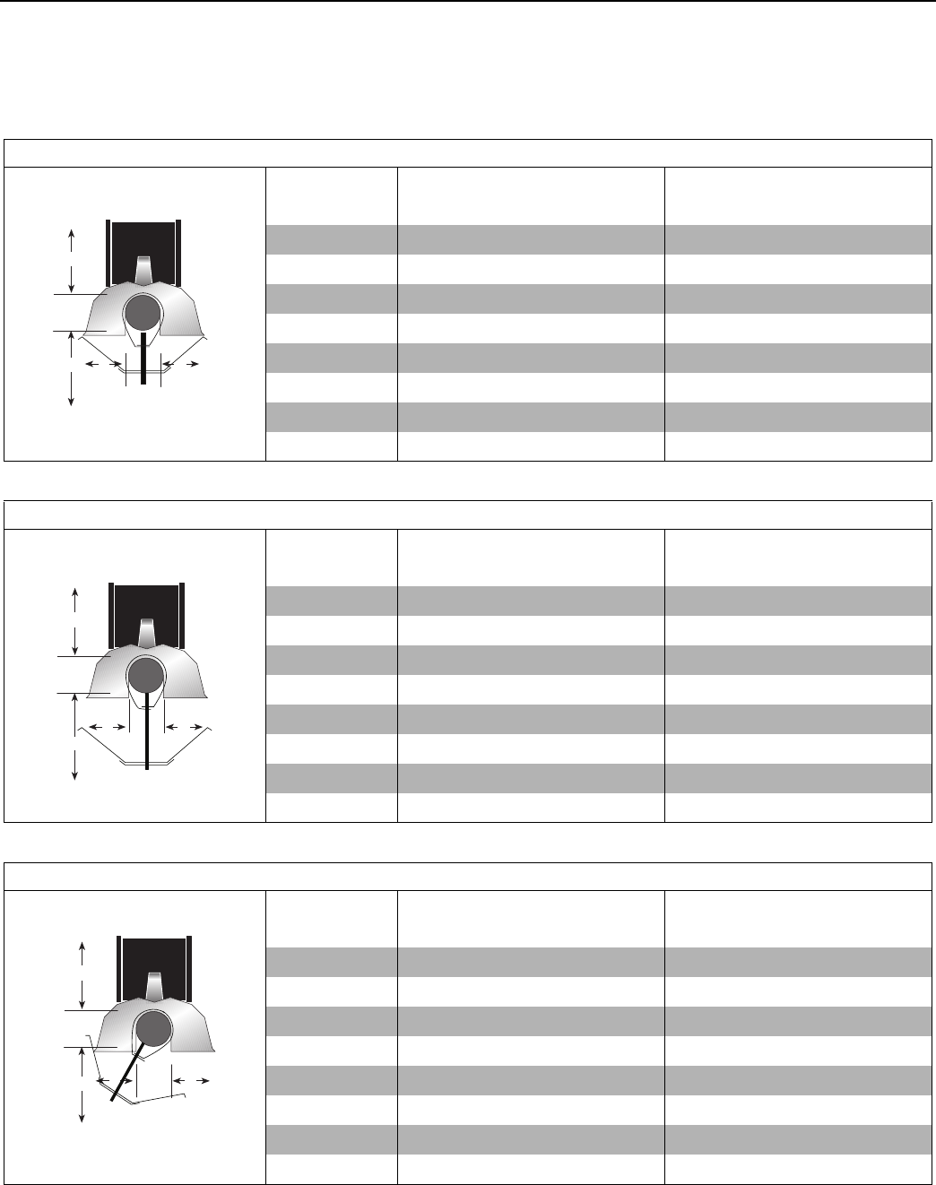
SECTION 3: CLEARANCES TO COMBUSTIBLES
7
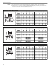
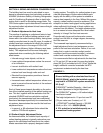
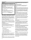
NOTE: 1. All dimensions are from the surfaces of all tubes, couplings, elbows, tees and crosses.
2. Clearances B, C and D can be reduced by 50% after 25' (7.5 m) of tubing downstream from
where the combustion chamber and the tube connect.
FIGURE 5: UNIVERSAL SHIELD, POSITION 1
(inches) (centimeters)
Model A B CDABCD
CRV-B-2 4 12 12 12 11 31 31 31
CRV-B-4 4 12 12 12 11 31 31 31
CRV-B-6 4 12 12 12 11 31 31 31
CRV-B-8 4 12 12 12 11 31 31 31
CRV-B-9 8 18 24 18 21 46 61 46
CRV-B-10 8 18241821466146
CRV-B-12 8 18 24 18 21 46 61 46
CRV-B-12A 8 18 24 18 21 46 61 46
C
A
B
D
FIGURE 6: UNIVERSAL SHIELD, POSITION 2
(inches) (centimeters)
Model A B CDABCD
CRV-B-2 4 24 48 24 11 61 122 61
CRV-B-4 4 24 48 24 11 61 122 61
CRV-B-6 4 24 48 24 11 61 122 61
CRV-B-8 4 24 48 24 11 61 122 61
CRV-B-9 4 36 48 36 11 92 122 92
CRV-B-10 4 36 48 36 11 92 122 92
CRV-B-12 4 36 48 36 11 92 122 92
CRV-B-12A 4 36 48 36 11 92 122 92
C
A
B
D
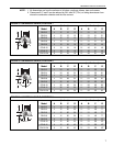
FIGURE 7: UNIVERSAL SHIELD, POSITION 3
(inches) (centimeters)
Model A B CDABCD
CRV-B-2 4 12 56 30 11 31 143 77
CRV-B-4 4 12 56 30 11 31 143 77
CRV-B-6 4 12 56 30 11 31 143 77
CRV-B-8 4 12 56 30 11 31 143 77
CRV-B-9 8 12 60 42 21 31 153 107
CRV-B-10 8 12 60 42 21 31 153 107
CRV-B-12 8 12 60 42 21 31 153 107
CRV-B-12A 8 12 60 42 21 31 153 107
C
A
B
D