


CRV-SERIES INSTALLATION, OPERATION AND SERVICE MANUAL
16
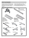
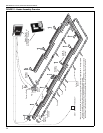
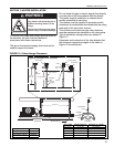
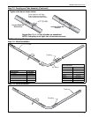
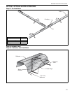
Step 7.1 Tube Installation
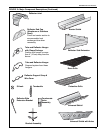
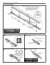
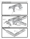
Step 7.2 Coupling and Tube Assembly
Combustion
Chamber
7' 6"
(229 cm)
Combustion
Chamber
NOTE: Tubing requires a downward slope of
1/2" (13 mm) per 20' (6 m) away from
burner. Tailpipe tubing requires a
downward slope of 1" (26 mm) per
20' (6 m) away from burner.
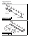
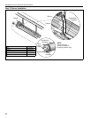
10'
maximum
(3 m)
End View
Weld
Seam
Bottom
of Tube
Hanger
Turnbuckles
Tube
Description Part Number
Tube 91409XXX
Turnbuckle 91903201
Tube/Reflector Hanger 03090100
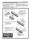
Tube
Tube
Orient coupling so that
the impact block is in the
2:00 or 10:00 oclock
positions.
Closed
Open
Tab
3" (8 cm) to
4" (10 cm)
Slide Bar/Coupling Lock
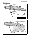
Coupling
Wide End
Coupling
Tube
Slide Bar/Coupling Lock
A
Close coupling with tab.
B
Start slide bar/coupling lock
onto coupling.
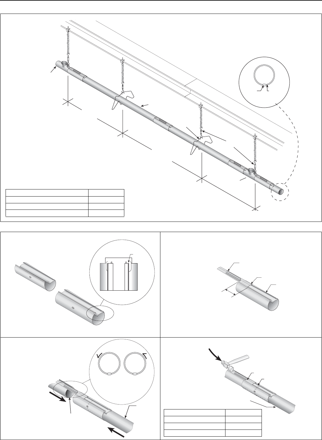
C
Insert tubes into coupling.
D
Tighten coupling to join tubes.
Description Part Number
Coupling 01329600
Slide Bar/Coupling Lock 01329700
Tube 91409XXX