


SECTION 10: OUTSIDE AIR SUPPLY
37
SECTION 10: OUTSIDE AIR SUPPLY
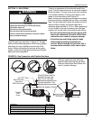
The CRV-Series system is approved for use with an
outside air system. Halogenated hydrocarbons or
other corrosive chemicals in the air can be drawn into
the equipment and seriously damage the system
components. Avoid the use of such chemical
compounds near the air inlet to the heaters.
IMPORTANT: If the building has a slight negative
pressure or contaminants are present in the air, an
outside combustion air supply to the heaters is
strongly recommended.
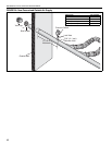
All joints and seams in the air supply system must be
airtight. Attach the filter housing to the burner
assembly using the wing nut provided.
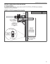
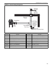
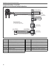
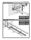
10.1 Pressurized
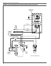
See Page 39, Figure 23 for a typical layout of a
pressurized air supply system.
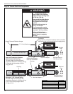
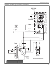
For pressurized outside air supplies, the outside air
blower motor has a pressure switch interlock that
must be used. Wire this switch in series with the
pump pressure switch. When using an outside air
blower with a ROBERTS GORDON
®
System Control
or ROBERTS GORDON
®
ULTRAVAC
™
control or
relay transformer, a separate load relay package is
required. Wire the control for the relay in parallel with
the pump. The outside air blower must have a
separate 20A, 120V power supply. See Page 38,
Figure 21 for outside air blower internal wiring
requirements.
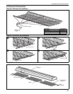
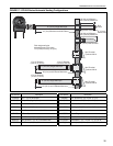
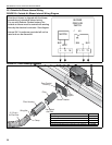
10.2 Non-Pressurized
For a non-pressurized outside air supply, a 4" (O.D.)
single wall pipe duct may be attached to the burner
and end vent. For length and duct sizing
requirements, see duct design rules in Figure 19. To
prevent condensation, insulate the outside air duct.
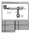
FIGURE 19: Duct Sizing
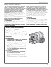
Outside Air System Design Requirements:
Blower Performance (90707501):
112 Flow Units
One outside air blower is required per each EP-100 or
EP-200 series pump and two outside air blowers may
be required for each EP-300 series pump. Outside air
blowers cannot be shared between two separate CRV-
Series systems.
Duct Design Rules:
- System should be designed so that the blower is
positioned closest to the highest flow
requirements (end vents).
- When a duct is carrying more than 40 flow units, it
must be at least 6" (15 cm) diameter.
Pressurized Systems
- 6" (15 cm) diameter duct must not exceed 120'
(36 m) total per system.
- 4" (10 cm) diameter duct must not exceed 120'
(36 m) per radiant branch.
Non Pressurized
- 6" (15 cm) diameter duct must not exceed 90'
(27 m) maximum 100 flow units
- 4" (10 cm) diameter duct must not exceed 90'
(27 m)
- Elbows are equivalent to 10' (3 m) of duct length.