


SECTION 7: HEATER I NSTALLATION
15
SECTION 7: HEATER INSTALLATION
To ensure your safety and comply with the terms of
the warranty, all units must be installed in
accordance with these instructions.
The gas or the electrical supply lines must not be
used to support the heater.
Do not locate the gas or electric supply lines directly
over the path of the flue products from the heater.
The heater must be installed in a location that is
readily accessible for servicing.
The heaters must be installed in accordance with
clearances to combustibles as indicated on the rating
plate and in this instruction manual.
The minimum and maximum gas inlet pressures
must be maintained as indicated on the rating plate.
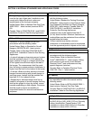
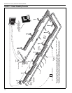
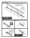
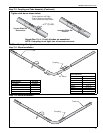
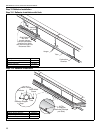
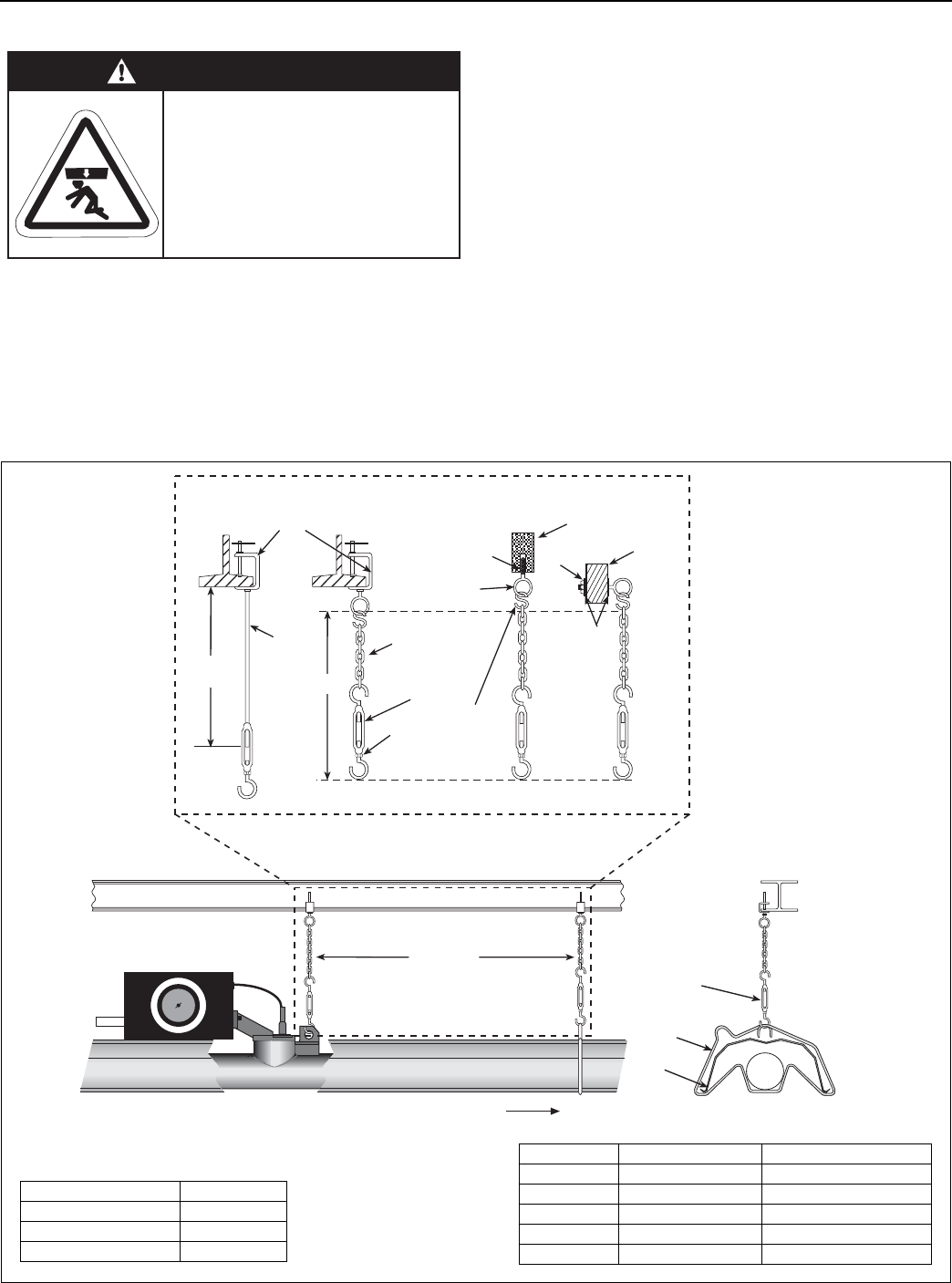
Typical installation configurations are shown in
Figure 12.
Expansion and contraction of the tube dictates that
the minimum suspension lengths in the table on
Figure 12 be maintained.
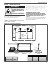
FIGURE 12: Critical Hanger Placement
WARNING
Suspension Hazard
Hang heater with materials with a
minimum working load of 75 lbs
(33 kg).
Failure of the supports can result
in death, injury or property
damage.
Side View Towards Pump
Typical Suspension Details
Turnbuckle
Rod 3/8"
Beam Clamp
Concrete Beam
Wood Beam
Washers
Locknut
Screw Hook
3/8"
24" min.
(61 cm)
"X" (See Table)
Locknut
(Typical)
Anchor
Hanger
Front View
S-Hook
Turnbuckle
Reflector
7'6" (2.3 m)
Chain size
3/16" minimum
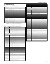
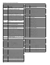
Description Part Number
Turnbuckle 91903201
S-Hook 91907302
Tube/Reflector Hanger 03090100
Run Length Typical Expansion Minimum “X” Length
50' (15 m) ±1" (3 cm) 12" (30 cm)
100' (31 m) ±2" (5 cm) 24" (61 cm)
150' (46 m) ±3" (8 cm) 36" (91 cm)
200' (61 m) ±4" (10 cm) 46" (122 cm)
250' (76 m) ±5" (13 cm) 57" (145 cm)