


SECTION 12: CONTROL M ETHODS
47
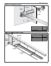
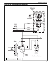
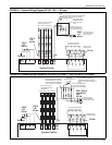
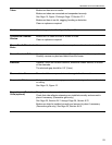
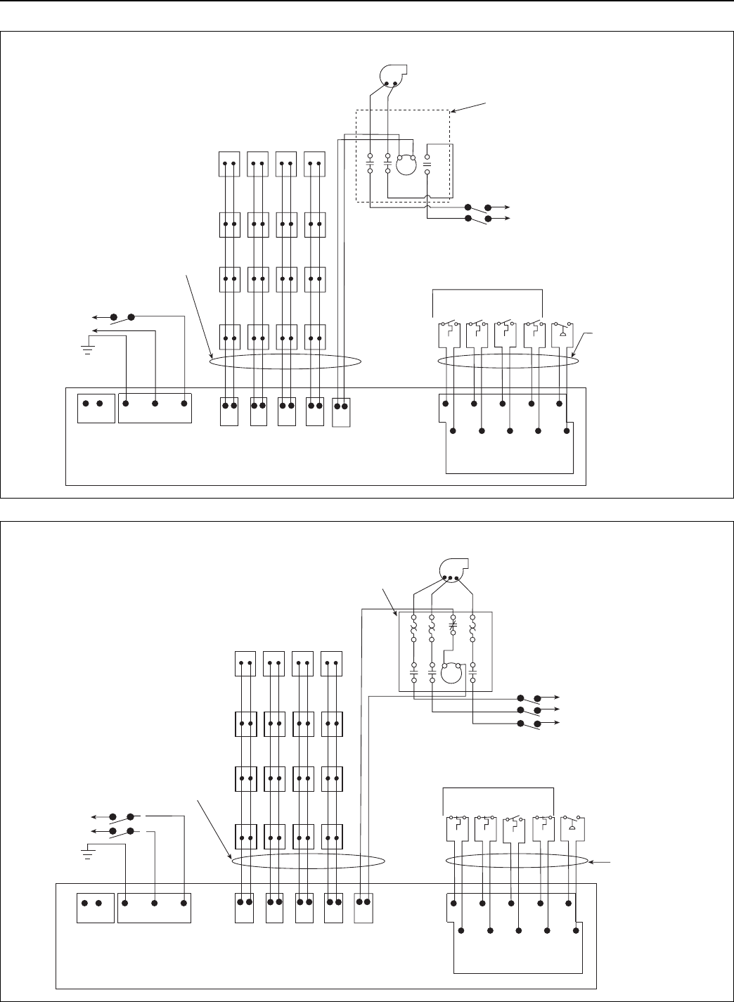
FIGURE 31: External Wiring Diagram EP-301 120 V 1 Ø Pump
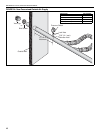
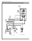
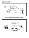
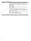
FIGURE 32: External Wiring Diagram EP-203 or EP-303 208 V - 230 V (or 460 V) 3 Ø Pump
System Control
12 Vdc
T1
T3
T2
T4
PS
C
C
C
C
C
Zone
1
Zone
2
Zone
4
Zone
3
230 V
1 Ø
60 Hz
PUMP
NL
Z1
Z2
Z3 Z4
NN
N
NLL
L
L
Zone 1Zone 2 Zone 3Zone 4
L
N
M
1
5
3
2
64
120 V
1 Ø
60 Hz
Individual supply for
pump rated for total
full load current.
120 V
1 Ø
60 Hz
Ground
L
N
G
L
N
Ground
All burners must be connected
to Ground. (Not shown.)
Do not directly connect the controller relay
terminals to the pump motor. Product
damage will result.
EP 301
Pump
The power supply for the
pump must be separate
from the controller supply.
IEC contactor (P/N
10050009) rated for
the EP 301 pump
motor
Low voltage thermostats
located in heated zone.
Pressure switch
located at pump.
System Control
C
T1
C
C
C
C
T3
T2
T4
PS
12 Vdc
120 V
1 Ø
60 Hz
Z1
Z2
Z3 Z4
NN
N
NLL
L
L
PUMP
NL
208 - 230 V
(or 460 V)
3 Ø
60 Hz
120 V
1 Ø
60 Hz
Ground
G
L
N
Ground
Individual supply
for pump rated for
total full load current.
L
N
EP-203 or
EP- 303 3 Ø Pump
M
OL
Motor starter (P/N 10050001)
rated for EP-203 pump motor;
motor starter (P/N 10050010)
rated for EP-303 pump motor.
Zone 1
All burners must be
connected to Ground.
(Not shown.)
Zone 2 Zone 3 Zone 4
L1
L3
L2
The power supply for the
pump must be separate
from the controller supply.
Do not directly connect the
controller relay terminals to the
pump motor. Product damage will
result.
Low voltage thermostats
located in heated zone.
Zone
1
Zone
2
Zone
4
Zone
3
Pressure switch
located at pump.