


SECTION 7: LINEAR HEATER INSTALLATION
13
SECTION 7: LINEAR HEATER INSTALLATION
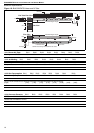
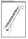
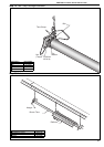
The figures in this section provide a general overview of
component placement in a BLACKHEAT® Linear
system. The location of some components
such as supports and couplings is crucial for proper
installation. Assemble the heater components as shown
on Page 14, Figure 17.
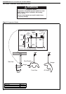
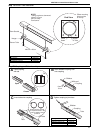
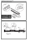
For optional reflector configurations for Linear heaters
See Page 4, Figure 2 through Page 5, Figure 8. Install
appropriate suspension hardware, beam clamps, chain or
rod at predetermined locations. Adjustments of chain
length will provide uniform pitch.
If any step is unclear, please contact Roberts-Gordon at
+ 61 [3] 9561 2100 [Hurll Nu-Way Pty Ltd]
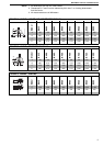
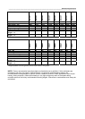
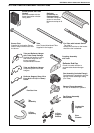
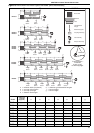
7.1 Linear Standard Parts List
* PVC coating must be removed prior to installation.
Part No. Description
BH15
BH20
BH25
BH30
BH35
BH40
BH45
BH50
BLACKHEAT®
Burner Assembly (Input and Fuel Varies)11111111
07260001 Fan Package XP 1 1 1 1 1 - - - -
07260002 Fan Package XP 2 - - - - 1 1 1 -
07260003Fan Package XP 3 -------1
03051101Burner Tube, 100 mm x 3048 mm 11111111
91409408Tube, 100 mm x 3048 mm -1122233
S5127WFan Tube, 100 mm x 3048 mm, with 3048 mm Swirler 1111111
S5134WFan Tube, 100 mm x 3048 mm with 2134 mm Swirler -------1
01329600Standard Coupling Assembly 12233344
01329700Coupling Lock 12233344
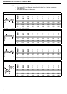
02750303Reflector, Aluminium, 2439 mm 34466677
S5163WReflector, Stainless Steel, 2439 mm (Optional)* 34466677
02750800Reflector End Cap, Aluminium 22222222
C2332B Reflector End Cap, Stainless (Optional)* 2 2 2 22222
03090100Tube and Reflector Hanger 34455566
01318901 Tube Clamp Package (including Nut, Washer & Bolt) 1 1 1 11111
91908004Wire Form 23355566
94320812 Screw #8 x 3/4 (3.9 x 19mm), (goes with 91908004) 4 6 6 10 10 10 12 12
03050000Reflector Support Strap 23355566
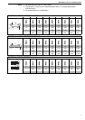
E0007576 Bow Shackle 3 4 4 55566
91107720 U-Clip Package (20 Pieces) 1 1 1 11111