


UHA STANDARD UNIT HEATER INSTALLATION OPERATION AND SERVICE MANUAL
40 of 51
SECTION 15: REPLACEMENT PARTS
See warnings and important information on Page
32, Section 13 before removing or replacing parts.
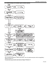
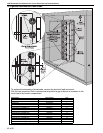
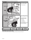
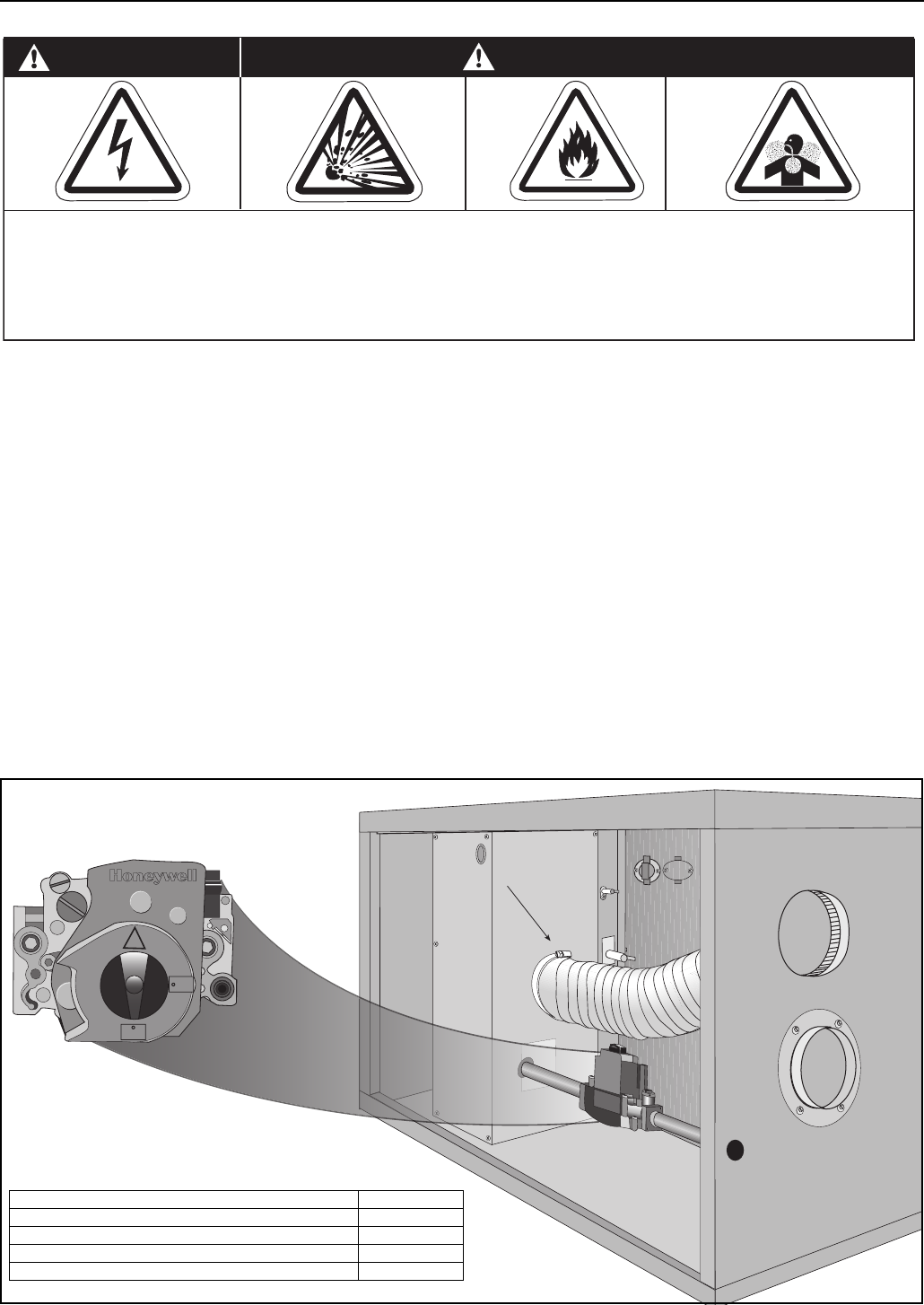
Burner Components
All serviceable burner parts are accessed by the
door on the side of the heater. Control door opens
via tooled access.
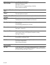
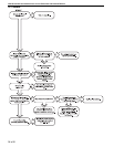
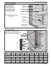
15.1 Gas Valve
Remove the gas supply pipe at the heater inlet.
Follow steps on Page 41, Section 15.2 and See
Page 41, Section 15.2.1 to remove gas valve/
manifold.
Replace in reverse order. Verify that the gas flow
direction of the valve is correct. Use a minimum
amount of gas seal on the thread joint. Check that
all the joints are leak free. Reset gas valve. See
Page 29, Section 11.2.2.
IT IS IMPORTANT THAT ONLY THE CORRECT
GAS VALVE IS USED WHEN REPLACING THESE
CONTROLS.
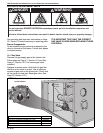
Carbon Monoxide Hazard
WARNING
Use only genuine ROBERTS GORDON
®
replacement parts per this installation, operation and
service manual.
Failure to follow these instructions can result in death, electric shock, injury or property damage.
Explosion Hazard
DANGER
Electrical Shock Hazard
Fire Hazard
½PSI IN
C
ON
OFF
Flexible
Air Duct
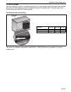
Description Part Number
Gas Valve, NG (Models UHA[X][S] 150 - 250) 90032505
Gas Valve, LP (Models UHA[X][S] 150 - 250) 90032506
Gas Valve, NG (Models UHA[X][S] 300 - 400) 90032520
Gas Valve, LP (Models UHA[X][S] 300 - 400) 90032521
NOTE: Seperated combustion
model shown.