


SECTION 15: REPLACEMENT PARTS
41 of 51
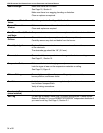
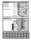
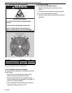
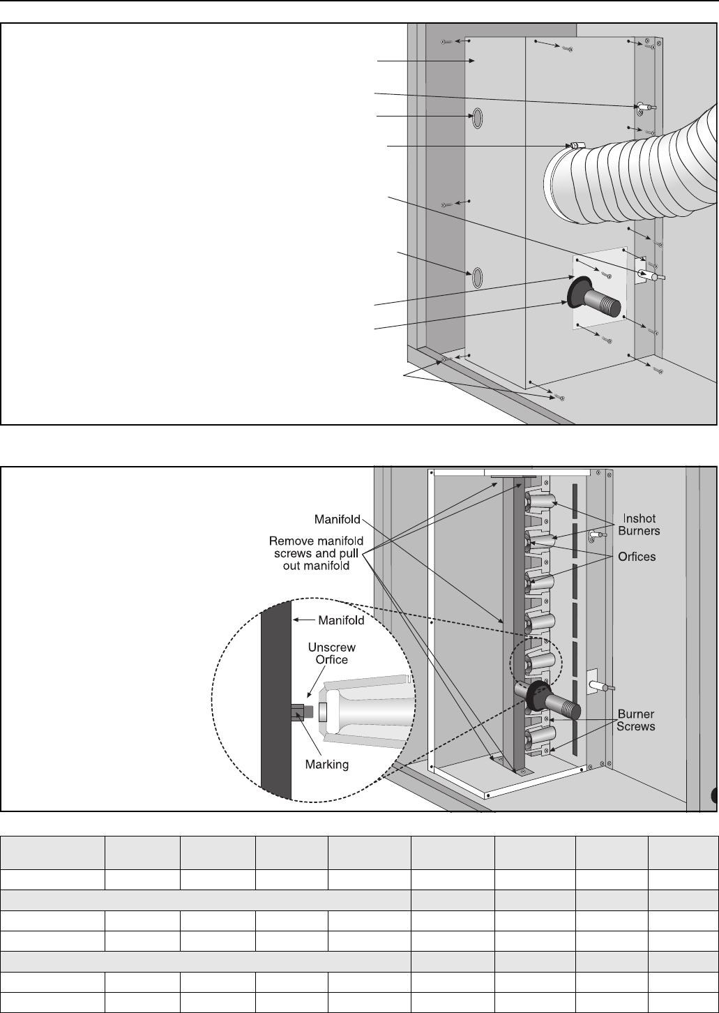
15.2 Burner Compartment
15.2.1 Burner Injectors
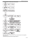
Remove flexible
air duct from spigot
Remove
access plate
Remove screws and
pull off burner
compartment cover
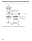
Viewing port
for flame probe
Viewing port
for ignition electrode
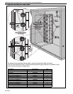
Flame Probe
Burner
Compartment
Cover
Rubber Seal
Ignition Electrode
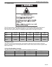
The burner compartment is
a sealed compartment.
Following any work,
re-seal the compartment
with the gas pipe rubber
seal fully in place and all
screws fitted and tight.
NOTE: Flexible duct only applies
for model UHAS.
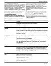
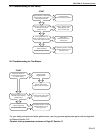
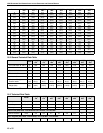
MODEL
UHA[X][S]
150
UHA[X][S]
175
UHA[X][S]
200
UHA[X][S]
225
UHA[X][S]
250
UHA[X][S]
300
UHA[X][S]
350
UHA[X][S]
400
Orifice Quantity 7 8 9 10 11 12 14 14
Natural Gas (G20)
Orifice Marking 43 43 2.25 mm 2.25 mm 2.25 mm 40 40 40
P/N 91930043 91930043 91930225 91930225 91930225 91930040 91930040 91930040
Propane (G31)
Orifice Marking 1.35 mm 1.35 mm 54 54 54 1.45 mm 53 53
P/N 91930135 91930135 91930054 91930054 91930054 91930145 91930053 91930053
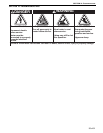
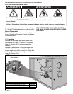
Ensure gas tight fitting of injectors.
Ensure correct alignment with burners.
Ensure all pipe joints are gas tight.