


UHA STANDARD UNIT HEATER INSTALLATION OPERATION AND SERVICE MANUAL
12 of 51
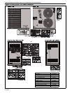
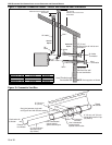
7.2.1 Standard Vented Heaters
(Models UHA[X] 150 - 400)
The vent must be fitted with a low resistance
terminal. See Page 13, Figure 6 through Page 14,
Figure 7. Standard vented heaters do not allow
outdoor air intake for combu stion air.
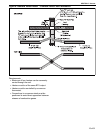
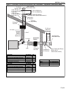
7.2.2 Separated Combustion Heaters
(Models UHA[X]S 150 - 400)
The heaters are designed to be installed as
separated combustion heaters. The vent and air
intake are run as separate pipes to the wall or roof
terminals. See Page 16, Figure 9. As an option, the
vent and air intake are run as separate pipes to a
concentric vent box and a concentric vent/air intake
pipe penetrates the wall or roof. See Page 16,
Figure 10 and Page 17, Figure 11.
For separated combustion installation, the vent and
air intake must be fitted with an individual and
correctly sized sealed system and the vent and air
intake must terminate at approved wall and roof
terminals.
Separated combustion units may not be common
vented. See Page 11, Section 7.
7.3 Unvented Operation
This heater is not approved to be installed in
residential buildings.
For unvented operation in commercial installations,
sufficient ventilation must be provided in the amount
of 4 cfm per 1000 Btu/h firing rate (United States); 3
cfm per 1000 Btu/h firing rate (Canada).
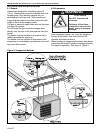
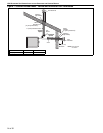
7.4 Horizontal Venting
Horizontally vented heaters must be individually
vented.
Vent pipe must be sloped ¼" (.6 cm) for every 1' (.3
m). For vent lengths greater than 5' (1.5 m),
condensation will form. Insulation is recommended
and condensation drains may be desired. For vents
pitched up toward the vent terminal, place the
condensation drain within 5' (1.5 m) of the heater.
In noncombustible walls only, vent terminal
(P/N 02537801-1P) may be used.
For 4'' (10 cm) vents in either combustible or
noncombustible walls, use vent terminal (P/N
90502100) or equivalent insulated vent terminal.
Follow the manufacturer's instructions for proper
installation.
Instead of an insulated vent terminal, a listed thimble
with 2" (5 cm) air gap, may be used with a 4" (10 cm)
vent cap (P/N 90502102).
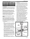
7.5 Vertical Venting
Vertically-vented standard-vented heaters can be
common vented (up to 4 heaters).
For vent lengths greater than 5' (1.5 m),
condensation will form. Insulation is recommended
and condensation drains may be desired. Vent from
the rear of the heater cabinet then run the vent
vertically and use a condensate drain at the bottom
of the vertical vent.
Vent pipe must be sloped 1/4'' (.6 cm) for every
1' (.3 m).
For 4'' (10 cm), an approved vent cap
(P/N 90502102) must be used.
For 6'' (15 cm) common vent, an approved vent cap
(P/N 90502103) must be used.
For common vertical venting of more than two
heaters, See Page 15, Figure 8.
A vent shall not extend less than 2' (.6m) above the
highest point where it passes through a flat roof of a
building.
7. 6 Le n gth Requirements
If using vent lengths greater than 5' (1.5 m),
condensation will form in the vent pipe. Insulation
and additional sealing measures (high temperature
silicone at all seams) are required.
The entire vent should be insulated with foil faced
fiberglass insulation (1/2" thick, 1-1/2# density
minimum).
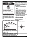
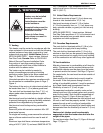
WARNING
Carbon Monoxide Hazard
Heaters may be installed
vented or unvented.
Vented heaters must be
vented outdoors.
Unvented heaters must be
installed according to the
installation manual.
Failure to follow these
instructions can result in
death or injury.