


SECTION 6: DUCT HEATER INSTALLATION
9 of 47
SECTION 6: DUCT HEATER INSTALLATION
6.1 General
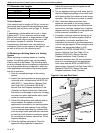
To connect the inlet and outlet ducts to the heater,
Duct-Mate or similar flanges may be slid over the
duct connector flanges supplied on the unit and
secured with screws. The connection to the duct
then can be made using the Duct-Mate clips. The
ducts must have removable access panels
upstream and downstream of the heater. These
panels must be of appropriate size and placement
so that smoke or reflected light could be observed to
indicate the presence of leaks in the heat
exchanger. Covers for these openings should be
sealed to prevent leakage.
Any transition into the inlet of the heater should be
smooth, with a taper of no more than 15 degrees. If
elbows are required, they should be of either broad
radius or fitted with properly designed air turns.
Consult a professional to ensure air turns are
properly designed.
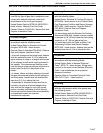
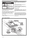
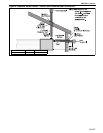
The heater must be installed on the positive
pressure side of the circulating air blower. Air flow
through the heater must be as shown on Page 9,
Figure 4 and may not be reversed. The air flo
w must
be adjusted such that it is within the acceptable
range shown on Page 9, Section 6.1.3. The
minimum inlet duct lengths shown on Page 9,
Section 6.1.1 should be observed. Pressure drop
through the heat exchanger at various air flows is
given on Page 9, Section 6.1.2.
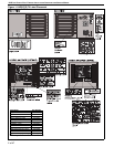
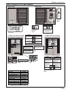
Figure 4: Air Flow Direction
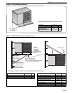
6.1.1 Minimum Inlet Duct Length
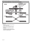
6.1.2 Temperature Rise and Pressure Drop Ranges
6.1.3 Air Flow and Temperature Rise Ranges
AIR FLOW
OUTLET DUCT
INLET DUCT
Model Duct Length Duct Size (W X H)
UHD[X][S] 75 32" (81 cm) 16 3/4" x 15 7/8" (43 cm x 40 cm)
UHD[X][S] 100 &125 37" (94 cm) 21 3/4" x 15 7/8" (55 cm x 40 cm)
UHD[X][S] 75 UHD[X][S] 100 UHD[X][S] 125
Airflow
(CFM)
Temperature
Rise (°F)
Pressure Drop
(in wc)
Airflow
(CFM)
Temperature
Rise (°F)
Pressure Drop
(in wc)
Airflow
(CFM)
Temperature
Rise (°F)
Pressure Drop
(in wc)
850 68 0.06 950 78 0.05 1,020 92 0.06
1,200 48 0.10 1,500 50 0.18 1,650 57 0.14
1,625 36 0.16 2,500 31 0.28 2,340 41 0.27
1,965 30 0.22 3,000 26 0.39 3,480 28 0.56
2,450 24 0.31 3,300 24 0.46 4,240 23 0.80
2,650 22 0.36 3,660 22 0.55 4,750 20 0.98
Model Rate Air Flow Temperature Rise
(Btu/h) Minimum (CFM) Maximum (CFM) Minimum (°F) Maximum (°F)
UHD[X][S] 75 75,000 850 2,650 22 68
UHD[X][S] 100 100,000 950 3,660 22 78
UHD[X][S] 125 125,000 1,020 4,750 20 92