


TABLE OF FIGURES
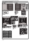
Figure 1: UHD [X][S] 75 Label Placement ................................2
Figure 2: UHD [X][S] 100-125 Label Placement........................3
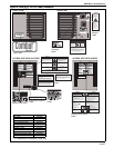
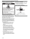
Figure 3: Clearances to Combustibles ......................................6
Figure 4: Air Flow Direction.......................................................9
Figure 5: Suspension Methods ...............................................10
Figure 6: Shelf-Mounting Methods.......................................... 11
Figure 7: Wall Shelf Mounting and Suspension ...................... 11
Figure 8: Vent and Roof Detail................................................14
Figure 9: Standard Vented Heater - Vertical and Horizontal
Vent Termination......................................................15
Figure 10: Standard Vented Heater - Common Vertical
Vent Termination......................................................15
Figure 11: Separated Combustion Heater - Vertical and
Horizontal Vent Termination.....................................16
Figure 12: Concentric Vent Box...............................................16
Figure 13: Concentric Vertical and Horizontal Vent
Termination - Separated Combustion Heater..........17
Figure 14: Gas Connection .....................................................20
Figure 15: Automatic Burner Control Sequence......................26
Figure 16: Gas Valve for Models UDH[X][S] 75 – 125.............26
Figure 17: Manual Reset Limit Switch.....................................29
Figure 18: LED Diagnostic Codes...........................................29