


SECTION 3: CRITICAL CONSIDERATIONS
5 of 47
SECTION 3: CRITICAL CONSIDERATIONS
3.1 Basic Information
UHD[X][S] heaters have automatic ignition burners
for ON/OFF operation only.
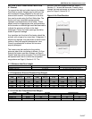
3.2 Manufactured Units
Gas-fired, power-vented duct furnace with tubular
heat exchanger. Units shall have a minimum of 82%
thermal efficiency. The standard unit shall consist of
a non-separated combustion design with an
aluminized heat exchanger. Design and heat
exchanger alternatives shall be offered as follows:
• Separated Combustion: A separated
combustion unit shall feature an enclosed,
sealed burner box. A piece of flexible air duct
connects this burner box to a flange on the
cabinet. Combustion air should be ducted from
outside the heated space, with the ductwork
connecting to the unit with the use of the flange.
• Stainless Steel Heat Exchanger: A stainless
steel heat exchanger unit shall consist of heat
exchanger tubes, heat exchanger tube supports,
heat exchanger tube plates and vent box
produced of 409 stainless steel.
The use of stainless steel heat exchanger is
recommended when air inlet temperatures are
below 40° F (4.4° C) or temperature rise is less
than 40° F (22.2° C) as condensation may form
on the heat exchanger resulting in corrosion that
may shorten its life.
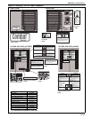
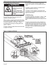
3.3 Location and Suspension
All models:
•Must be installed indoors.
•Must be installed on the positive pressure side of
the air circulation blower.
•Must be installed in a level position with
horizontal discharge.
• May be mounted on a shelf of non-combustible
material using shelf mounting brackets.(See
Page 11, Figure 6 and Page 11, Figure 7 for
details.)
• Drop rods must be a minimum of 3/8" diameter
mild steel. Four suspension points (3/8" nuts)
are located on top of the heater.
• May be suspended from above (See Page 10,
Figure 5) or from wall brackets of sufficient
strength to support the heater as listed in the
Technical Data Table on Page 45, Section 16.2.
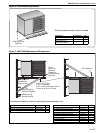
•Must be installed in a manner which allows
access to all serviceable components. See Page
6, Figure 3 for details.
3.4 Minimum Required Installation Clearances
Clearances around the heater and vent must be as
indicated on Page 6, Figure 3
and Page 14, Figure 8
to ensure access for servicing, and correct
operation.
3.5 Ventilation
It is important to ensure that there is adequate air
space around the heater to supply air for
combustion, ventilation and distribution in
accordance with local and national codes. See Page
12, Section 7.
3.6 Gas Supply
It is important that the gas supply pipe is sized
correctly to provide the inlet pressure as stated on
the heater data plate. The gas supply pipe and
electrical connections must not support any of the
heater's weight. See Page 20, Section 9.
3.7 Electrical Supply
A permanent 120 V /1 Ø/60 Hz electrical supply is
required for the main electrical power. The heater
also requires suitable controls in accordance with
Page 22, Section 10.
3.8 Vent
Choose heater orientation to allow for proper
location of the vent. Each heater must be fitted with
a correctly sized sealed vent system.
If vented horizontally, no other appliance may be
connected to the vent. See Page 12, Section 7.