


PG 5
PG 6
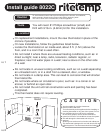
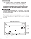
4 Before you Connect Wires
Caution
Do not allow wires to touch each other or parts on thermostat.
Wires must be routed through the hole in the back plate, below the
terminal block, or they will hit parts on the cover.
Please follow these guidelines for safe and secure wire connections.
Determine which step-by-step wiring diagram you should use. Make sure your
wires are labeled. This may require you to find the 'other end' connection for each
wire on your heating or air conditioning equipment and read the label there.
If you have a wire marked "C" its connection is optional. If you do connect it the
thermostat will draw power from the C wire and this will extend battery life.
If you have zoned heating/cooling systems with multiple thermostats. Please
refer to the website at www.ritetemp-thermostats.com for installation details or call
1-888-515-2585 for assistance.
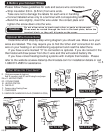
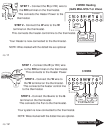
Optional Wire Connections
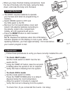
What Wires Do You Have?
Strip insulation 3/8 in. (9.5mm) from wire ends.
Take care not to damage the labels for each wire in handling.
Connect labeled wires only to a terminal with corresponding letter.
Bend the wire slightly, insert the wire under the contact plate and
tighten the screw down onto the wire.
RH
G
Y
W
C
From Furnace
And AC unit
R
or
B
G
Y
R
C
From single stage
heat pump
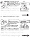
O
or
RC
G
Y
W
C
From Furnace
And AC unit
RH
Go To Page 13
Go To Page 14
Go To Page 12
RH
W
C
From Furnace
G
W
RH
R
or
From Furnace
Go To Page 11
C
Go To Page 15
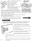
R - Single source power for heat/cool
Note: R connects to both RC and RH using the red jump er
RH or R - HEATING POWER
RC - COOLING POWER
W - HEATING CONTROL
G - FAN RELAY
C - Common side of Heating Power
Y - COMPRESSOR
O - DAMPER OR CHANGEOVER VALVE (POWERED IN COOL)
or R